


Basic Dual Polarity Power Supply
#dual polarity
#transformer
#diode rectifier
#electrolytic capacitor
#voltage regulation
#center tapped
#bridge rectifier
#DC power
#circuit diagram
#basic electronics
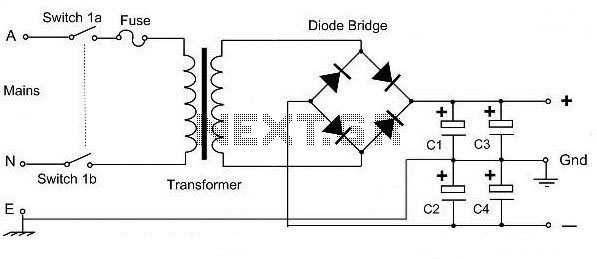
Description: This is a basic dual polarity power supply circuit diagram. It requires the following components: a center-tapped transformer, four diode rectifiers (or one diode bridge), and four electrolytic capacitors. The value of each component is essential for the circuit's performance.
The dual polarity power supply circuit is designed to provide both positive and negative voltage outputs from a single transformer. The center-tapped transformer is the key component, featuring a primary winding connected to the AC mains and two equal secondary windings that produce two outputs, typically referred to as the positive and negative voltages.
The circuit utilizes four diodes arranged in a full-wave rectifier configuration. This setup can also be replaced by a single diode bridge rectifier, which simplifies the design by integrating the four diodes into one component. The rectification process converts the alternating current (AC) from the transformer into direct current (DC), producing both positive and negative voltages relative to the center tap.
Following the rectification, four electrolytic capacitors are employed to smooth the output voltage. These capacitors store charge and help reduce voltage ripple, ensuring a more stable DC output. The values of the capacitors should be selected based on the load requirements and the desired level of ripple voltage. Typically, larger capacitance values lead to lower ripple, but they also affect the response time of the power supply under load changes.
Overall, this dual polarity power supply circuit is fundamental in various electronic applications, including operational amplifiers, analog signal processing, and other devices that require dual voltage supplies. Proper selection of each component, including the transformer ratings, diode specifications, and capacitor values, is critical to the successful implementation of this circuit.This is a very basic dual polarity power supply circuit diagram. It just need the following components: - A Center Tapped Transformer - Diode rectifier 4 units (or diode bridge 1 unit) - Electrolityc capacitor 4 units The value of each comp..
The dual polarity power supply circuit is designed to provide both positive and negative voltage outputs from a single transformer. The center-tapped transformer is the key component, featuring a primary winding connected to the AC mains and two equal secondary windings that produce two outputs, typically referred to as the positive and negative voltages.
The circuit utilizes four diodes arranged in a full-wave rectifier configuration. This setup can also be replaced by a single diode bridge rectifier, which simplifies the design by integrating the four diodes into one component. The rectification process converts the alternating current (AC) from the transformer into direct current (DC), producing both positive and negative voltages relative to the center tap.
Following the rectification, four electrolytic capacitors are employed to smooth the output voltage. These capacitors store charge and help reduce voltage ripple, ensuring a more stable DC output. The values of the capacitors should be selected based on the load requirements and the desired level of ripple voltage. Typically, larger capacitance values lead to lower ripple, but they also affect the response time of the power supply under load changes.
Overall, this dual polarity power supply circuit is fundamental in various electronic applications, including operational amplifiers, analog signal processing, and other devices that require dual voltage supplies. Proper selection of each component, including the transformer ratings, diode specifications, and capacitor values, is critical to the successful implementation of this circuit.This is a very basic dual polarity power supply circuit diagram. It just need the following components: - A Center Tapped Transformer - Diode rectifier 4 units (or diode bridge 1 unit) - Electrolityc capacitor 4 units The value of each comp..

Regulator circuit silicon resistor formed
The simple voltage regulator circuit consists of a silicon regulator and a resistor. It is designed to rectify and filter DC voltage, as illustrated in the accompanying figure. The voltage regulator is connected in parallel with the load, and the...

variable voltage and current power supply
An alternative method for utilizing operational amplifiers (op-amps) to regulate a power supply is illustrated below. The power transformer necessitates an additional winding to provide the op-amps with a bipolar voltage of +/- 8 volts. This negative voltage is also...
Line-operated-amplifier
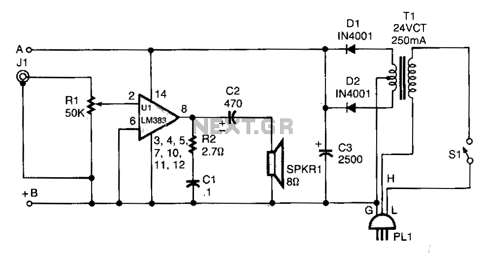
T1 isolates the unit from the line and has a 24-V, center-tapped secondary. The output of the transformer is rectified by diodes D1 and D2 and filtered by capacitor C3 to provide 15 to 18 Vdc. The LM383 has built-in...
transformer circuit
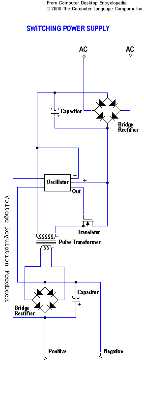
A static device that couples two circuits to transfer alternating current (AC) from one circuit to another through electromagnetic induction. The current maintains the same frequency but may vary in voltage, phase, or impedance values. A transformer consists of two...

power Voltage supply clipping to <=3.3V
Supply it with a Li-Ion cell, which has a voltage range of 2.7 to 4.2V. The complexity of a buck/boost converter is not desired. While it is possible to regulate the voltage down to anything below 2.5V, it would be...

capacitor Explaining a car voltage regulator circuit
The circuit regulates approximately 12V from the car battery down to 5V for use by an Atmel AVR microcontroller. The presence of two capacitors on each side of the linear regulator LM7805 raises questions regarding their purpose. It is suggested...

Design and making of the stabilized voltage supply of switch
Under the loading condition of the resistance, the output voltage (Uo) variable range is from 30V to 36V, with a maximum output current (Imax) of 2A. When the input voltage (U2) changes from 15V to 21V, the voltage regulation factor...

Classic car battery charging circuit diagram
The circuit operates after a transformer, utilizing a bridge rectifier and conditioning for battery charging. The charging current transformer can be easily adjusted to provide approximately 12V at 100Ah battery charging. The required charging current is 10A, and a 150VA...

DC Voltage Regulator Circuit
This circuit regulates a DC power output and has a wide range of applications. It can be utilized to control the speed of a motor, a pump, a toy train, or the brightness of an LED or lamp. Essentially, it...