


Basic UPS Power Supplys
#UPS
#regulated voltage
#unregulated voltage
#battery backup
#5V
#12V
#voltage regulation
#backup power
#circuit protection

Description: This circuit represents a basic version of a commercial uninterruptible power supply (UPS), providing a constant regulated output of 5 volts and an unregulated 12-volt supply. In case of a power failure, the battery seamlessly takes over, ensuring there are no voltage spikes on the regulated supply. The design allows for adaptation to other regulated and unregulated voltages by utilizing different regulators and batteries. For instance, to achieve a 15-volt regulated output, two 12-volt batteries can be connected in series along with a 7815 voltage regulator. The circuit offers considerable flexibility. Transformer TR1 is designed with a primary winding compatible with the local electrical supply, which is 240 volts in the UK. The secondary winding should be rated for at least 12 volts at 2 amps, but higher ratings, such as 15 volts, are permissible. Fuse FS1 is a slow-blow type, providing protection against short circuits on the output or a malfunctioning cell in the rechargeable battery. LED1 illuminates only when the mains electricity is present; during a power failure, the LED turns off while the battery maintains the output voltage. The circuit diagram simulates operation with mains power applied: between terminals VP1 and VP3, the nominal unregulated supply is available, and a 5-volt regulated supply is present between VP1 and VP2. Resistor R1 and diode D1 form the charging path for battery B1, while diodes D1 and D3 prevent LED1 from lighting under power failure conditions. The battery is intended for trickle charging, with the charging current regulated by D2; its absence would allow the battery to charge from the full supply voltage without current limiting, risking damage and overheating of certain rechargeable batteries. The circuit's ability to sustain the regulated supply during a power outage is contingent upon the load drawn from the UPS and the ampere-hour capacity of the battery. For example, using a 7Ah 12-volt battery with a 0.5-amp load from the 5-volt regulator (and no load from the unregulated supply) would allow the regulated output to be maintained for approximately 14 hours. Batteries with greater ampere-hour capacities will provide longer standby times, and vice versa.
This circuit functions as a versatile UPS solution, capable of maintaining a stable output under varying conditions. The integration of a transformer, appropriate fuses, and diodes ensures safe operation and protection against common electrical faults. The design's adaptability allows for the use of different battery types and voltage regulators, making it suitable for various applications where uninterrupted power is critical. The implementation of a trickle charging mechanism protects the battery from overcharging, thereby extending its lifespan and reliability. The careful selection of components, such as the slow-blow fuse and specific diodes, enhances the circuit's resilience against short circuits and power failures. Overall, the circuit provides a reliable means to ensure continuous power supply, making it an essential component in environments where power stability is paramount.This circuit is a simple form of the commercial UPS, the circuit provides a constant regulated 5 Volt output and an unregulated 12 Volt supply. In the event of electrical supply line failure the battery takes over, with no spikes on the regulated supply.
This circuit can be adapted for other regulated and unregulated voltages by using different re gulators and batteries. For a 15 Volt regulated supply use two 12 Volt batteries in series and a 7815 regulator. There is a lot of flexibility in this circuit. TR1 has a primary matched to the local electrical supply which is 240 Volts in the UK. The secondary winding should be rated at least 12 Volts at 2 amp, but can be higher, for example 15 Volts. FS1 is a slow blow type and protects against short circuits on the output, or indeed a faulty cell in a rechargeable battery.
LED 1 will light ONLY when the electricity supply is present, with a power failure the LED will go out and output voltage is maintained by the battery. The circuit below simulates a working circuit with mains power applied: Between terminals VP1 and VP3 the nominal unregulated supply is available and a 5 Volt regulated supply between VP1 and VP2.
Resistor R1 and D1 are the charging path for battery B1. D1 and D3 prevent LED1 being illuminated under power fail conditions. The battery is designed to be trickle charged, charging current defined as :- D2 must be included in the circuit, without D2 the battery would charge from the full supply voltage without current limit, which would cause damage and overheating of some rechargeable batteries. An electrical power outage is simulated below: The ability to maintain the regulated supply with no electrical supply depends on the load taken from the UPS and also the Ampere hour capacity of the battery.
If you were using a 7A/h 12 Volt battery and load from the 5 Volt regulator was 0. 5 Amp (and no load from the unregulated supply) then the regulated supply would be maintained for around 14 hours. Greater A/h capacity batteries would provide a longer standby time, and vice versa.
This circuit functions as a versatile UPS solution, capable of maintaining a stable output under varying conditions. The integration of a transformer, appropriate fuses, and diodes ensures safe operation and protection against common electrical faults. The design's adaptability allows for the use of different battery types and voltage regulators, making it suitable for various applications where uninterrupted power is critical. The implementation of a trickle charging mechanism protects the battery from overcharging, thereby extending its lifespan and reliability. The careful selection of components, such as the slow-blow fuse and specific diodes, enhances the circuit's resilience against short circuits and power failures. Overall, the circuit provides a reliable means to ensure continuous power supply, making it an essential component in environments where power stability is paramount.This circuit is a simple form of the commercial UPS, the circuit provides a constant regulated 5 Volt output and an unregulated 12 Volt supply. In the event of electrical supply line failure the battery takes over, with no spikes on the regulated supply.
This circuit can be adapted for other regulated and unregulated voltages by using different re gulators and batteries. For a 15 Volt regulated supply use two 12 Volt batteries in series and a 7815 regulator. There is a lot of flexibility in this circuit. TR1 has a primary matched to the local electrical supply which is 240 Volts in the UK. The secondary winding should be rated at least 12 Volts at 2 amp, but can be higher, for example 15 Volts. FS1 is a slow blow type and protects against short circuits on the output, or indeed a faulty cell in a rechargeable battery.
LED 1 will light ONLY when the electricity supply is present, with a power failure the LED will go out and output voltage is maintained by the battery. The circuit below simulates a working circuit with mains power applied: Between terminals VP1 and VP3 the nominal unregulated supply is available and a 5 Volt regulated supply between VP1 and VP2.
Resistor R1 and D1 are the charging path for battery B1. D1 and D3 prevent LED1 being illuminated under power fail conditions. The battery is designed to be trickle charged, charging current defined as :- D2 must be included in the circuit, without D2 the battery would charge from the full supply voltage without current limit, which would cause damage and overheating of some rechargeable batteries. An electrical power outage is simulated below: The ability to maintain the regulated supply with no electrical supply depends on the load taken from the UPS and also the Ampere hour capacity of the battery.
If you were using a 7A/h 12 Volt battery and load from the 5 Volt regulator was 0. 5 Amp (and no load from the unregulated supply) then the regulated supply would be maintained for around 14 hours. Greater A/h capacity batteries would provide a longer standby time, and vice versa.

Power Supply 0-30V / 0-2A
The basic requirements for a laboratory power supply are to provide the necessary voltages and currents with low output resistance, low noise, minimal ripple, and good stabilization. These requirements are addressed within the circuit design. Many power supplies incorporate electronic...

12V Fluorescent lamp flashing circuit
This is a flashing blink circuit designed for 12V applications. It utilizes a small-sized fluorescent lamp and operates through a relay that modifies the circuit from DC to AC.
The flashing blink circuit operates at a voltage of 12V, making it...
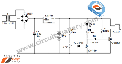
Simple battery charger circuit and battery level indicator with low battery recharge alarm
This is a straightforward 12V rechargeable smart battery charger circuit. It can be utilized as a charger for car batteries, inverter batteries, emergency light batteries, and more. An automatic indicator alarm circuit accompanies this battery charger schematic. The primary benefit...

Litter Box with 12V pc fan
Not every new use of technology requires a microcontroller. This one uses a 12 volt computer fan from CompUSA, a snap close food box from Walmart, some PVC pipe from Home Depot, and a large plastic storage container from Big...
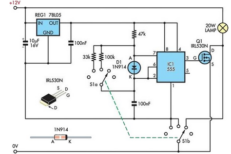
12V Halogen Dimmer
A 12V 20W halogen lamp (MR16) and a 4.2Ah SLA battery are utilized in a bike light system. Due to the limited lifespan of the battery at this power rating, a cost-effective light dimmer was designed to reduce battery consumption...

12V Car Battery Charger circuit
The following circuit diagram represents a battery charger designed for a 12V car battery. This circuit includes overcharging protection, which automatically disconnects the charging circuit. Unlike typical battery chargers that continuously supply a few amperes to the battery while powered...

12V Battery Charger for Lead/Acid
The battery charger circuit described is straightforward to assemble, requiring only a few inexpensive components and an additional winding on the power transformer (or a separate transformer). Since this charger operates independently of sound reproduction, there are no stringent requirements...

12V Halogen Dimmer
A 12V 20W halogen lamp (MR16) is utilized in a bike light system powered by a 4.2Ah SLA battery. Due to the limited battery life at this power rating, a cost-effective light dimmer has been designed to reduce battery drain,...

5V to 2.5V voltage regulator circuit
A 5V to 2.5V voltage regulator circuit is designed for use in computer motherboards. At its core, this circuit utilizes the RT9202 power management chip. The RT9202 functions as a switching pulse generating circuit, which, upon startup, converts a 5V...