


Bench top power supply
#bench top power supply
#transformer
#diode bridge
#filter capacitors
#voltage regulator
#723 IC
#pre-regulator
#LED indicator
#current-limiting resistor

Description: A tapped transformer drives a diode bridge (D1-D4) and two 2500 µF filter capacitors (C1 and C2), which provide a no-load voltage of 37 or 47 volts, depending on the position of switch S2a. The unregulated DC is then fed to a pre-regulator stage composed of Q1 and D5. These components protect IC1 (the 723) from an over-voltage condition, as the 723 cannot handle more than 40 volts. The LED (LED1) and its 2.2 kΩ current-limiting resistor (R1) provide on/off indication. The current through the LED varies slightly according to the transformer tap selected, but this is of no significant consequence. The series-pass transistor in IC1 drives voltage-follower Q2, providing current amplification. The transistor can handle considerable power, with a maximum collector current of 15 amps and a maximum VCE of 70 V, both of which are more than adequate for this power supply.
The circuit begins with a tapped transformer that provides multiple voltage outputs based on the selected tap via switch S2a. The diode bridge rectifies the AC voltage produced by the transformer into a pulsating DC voltage. The two 2500 µF filter capacitors (C1 and C2) smooth out the rectified output, yielding a stable DC voltage of either 37 volts or 47 volts, depending on the transformer tap selected.
The unregulated DC voltage is then directed to a pre-regulator stage composed of a transistor (Q1) and a Zener diode (D5). This stage is crucial for protecting the voltage regulator IC (IC1, the 723) from voltage levels exceeding its maximum rating of 40 volts. The Zener diode clamps the voltage to a safe level, ensuring that IC1 operates within its specified limits.
An LED (LED1) connected with a 2.2 kΩ current-limiting resistor (R1) serves as a power indicator, illuminating when the circuit is powered. The LED's brightness may vary slightly with different transformer taps, but this variation does not significantly impact the overall functionality of the circuit.
The 723 voltage regulator IC is designed to maintain a constant output voltage by adjusting the pass transistor (Q2) in response to load changes. Q2, configured as a voltage follower, provides current amplification, allowing the circuit to deliver sufficient current to the load. With a maximum collector current rating of 15 amps and a maximum VCE of 70 volts, Q2 is well-suited for this application, ensuring reliable performance under varying load conditions. This design effectively combines voltage regulation and power handling capabilities, making it suitable for various electronic applications.A tapped transformer drives a diode bridge (D1-D4) and two 2500 µ¥ filter capacitors (Cl and C2), that provide a no-load voltage of 37 or 47 volts, depending upon the position of switch S2a. The unregulated dc is then fed to a pre-regulator stage composed of Ql and D5. Those components protect IC1 (the 723) from an over-voltage condition; the 723 can't handle more than 40 volts.
The LED (LED1) and its 2.2 k current-limiting resistor (Rl) provide on/off indication. The current through the LED varies slightly according to the transformer tap selected, but that's of no real consequence. The series-pass transistor in IC1 drives voltage-follower Q2, providing current amplification. The transistor can handle lots of power. It has a maximum collector current of 15 amps and a maximum VCE of 70 V, both of which are more than adequate for our supply.
The circuit begins with a tapped transformer that provides multiple voltage outputs based on the selected tap via switch S2a. The diode bridge rectifies the AC voltage produced by the transformer into a pulsating DC voltage. The two 2500 µF filter capacitors (C1 and C2) smooth out the rectified output, yielding a stable DC voltage of either 37 volts or 47 volts, depending on the transformer tap selected.
The unregulated DC voltage is then directed to a pre-regulator stage composed of a transistor (Q1) and a Zener diode (D5). This stage is crucial for protecting the voltage regulator IC (IC1, the 723) from voltage levels exceeding its maximum rating of 40 volts. The Zener diode clamps the voltage to a safe level, ensuring that IC1 operates within its specified limits.
An LED (LED1) connected with a 2.2 kΩ current-limiting resistor (R1) serves as a power indicator, illuminating when the circuit is powered. The LED's brightness may vary slightly with different transformer taps, but this variation does not significantly impact the overall functionality of the circuit.
The 723 voltage regulator IC is designed to maintain a constant output voltage by adjusting the pass transistor (Q2) in response to load changes. Q2, configured as a voltage follower, provides current amplification, allowing the circuit to deliver sufficient current to the load. With a maximum collector current rating of 15 amps and a maximum VCE of 70 volts, Q2 is well-suited for this application, ensuring reliable performance under varying load conditions. This design effectively combines voltage regulation and power handling capabilities, making it suitable for various electronic applications.A tapped transformer drives a diode bridge (D1-D4) and two 2500 µ¥ filter capacitors (Cl and C2), that provide a no-load voltage of 37 or 47 volts, depending upon the position of switch S2a. The unregulated dc is then fed to a pre-regulator stage composed of Ql and D5. Those components protect IC1 (the 723) from an over-voltage condition; the 723 can't handle more than 40 volts.
The LED (LED1) and its 2.2 k current-limiting resistor (Rl) provide on/off indication. The current through the LED varies slightly according to the transformer tap selected, but that's of no real consequence. The series-pass transistor in IC1 drives voltage-follower Q2, providing current amplification. The transistor can handle lots of power. It has a maximum collector current of 15 amps and a maximum VCE of 70 V, both of which are more than adequate for our supply.

Thrifty Voltage Regulator
One of the drawbacks of a three-pin voltage regulator is that the input voltage needs to be 2.5 to 3 V higher than the output voltage. This makes these integrated regulators unsuitable for battery power supplies. For instance, if the...

Dual Voltage 12V Power Supply
The following circuit diagram of a dual voltage power supply can be used for miscellaneous applications. It requires a few components to build. The most important components of this circuit are regulators: 1: (AN) 7812 and 2: (AN) 7912. AN7812...

12-16V-converter
Many devices operate from a car's 12-V electrical system. Some require 12 V, while others need a lower voltage. An automobile battery's output can vary from 12 to 13.8 V under normal circumstances. The load requirements of the device may...

voltage regulator circuit with pass
This is a simple design for a voltage regulator circuit using a pass transistor. The design is built around the LM317T. The output current of the LM317T can be increased by incorporating an additional power transistor to share a portion...
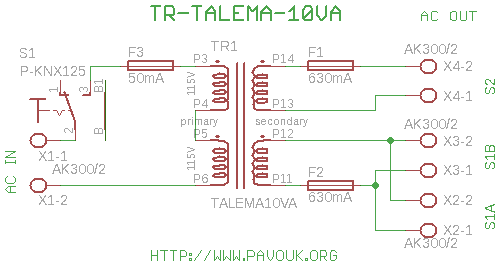
Talema 10VA transformer board
All DAC boards include a power supply section. It is sufficient to connect only a power transformer. This board is designed for a toroidal 10VA transformer manufactured by Talema, which features pins for PCB connection and exhibits minimal electromagnetic field...

ISL62391
The ISL62391 controller generates supply voltage for battery-powered systems. It includes two pulse-width modulation (PWM) controllers, adjustable from 0.6V to 5.5V, and a linear regulator (LDO3) that generates a fixed 3.3V and can deliver up to 100mA. The ISL62391 includes...
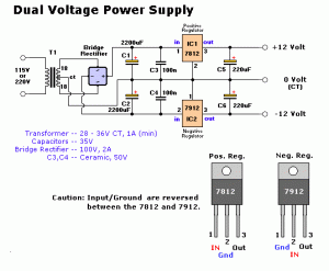
12V DC Dual Power Supply Circuit with IC 7812&7912
The 78W series voltage regulators are designed to handle an input voltage of approximately 35V, while the 24V type can withstand up to 40V. It should be noted that these regulators will not operate effectively with a significant input-output voltage...

12 Volt 30 Amp Power Supply
This power supply utilizes a single 7812 integrated circuit (IC) voltage regulator in conjunction with multiple external pass transistors to provide output load currents of up to 30 amps.
The circuit design incorporates a 7812 voltage regulator, which is known for...

CENTER TAPPED TRANSFORMER AUDIO OSCILLATOR
The oscillator circuit employs a center-tapped transistor output transformer that functions as a load for the collector of Q1, provides a feedback signal to the base, and acts as the output winding to drive the speaker. Resistor R1 supplies DC...