


Breaker control signal circuit manually
#breaker
#control signal
#AC power
#manual operation
#CS2
#circuit
#electrical
#switch
#power control

Description: The CS2 type is a manually operated breaker mechanism commonly utilized for AC power operation and manual control signal circuits, as depicted in Figure 6-68. The circuit includes various components: wc for small signal bus control, QF for auxiliary contacts of the circuit breaker, YR for the temporary trip coil, QM for auxiliary contacts of the manual operating mechanism, Hi as a green indicator light, H2 as a red indicator, and Ri and R2 as current limiting resistors.
The CS2 type manually operated breaker mechanism is an essential component in electrical systems that require reliable operation and control. This mechanism is designed to facilitate the manual interruption and restoration of electrical circuits, ensuring safety and functionality in various applications. The AC power operation allows for integration into alternating current systems, making it versatile for different environments.
The control signal circuit, as illustrated in Figure 6-68, incorporates several key elements that work together to manage the operation of the breaker. The 'wc' component serves as the control signal for a small signal bus, enabling communication and control over the circuit's operation. The auxiliary contacts, represented by 'QF', play a crucial role in providing feedback and ensuring the proper functioning of the circuit breaker during operation.
The 'YR' component refers to a temporary trip coil, which is activated under specific conditions to interrupt the circuit, protecting against overloads or faults. This feature is vital for maintaining system integrity and preventing damage to connected equipment. The 'QM' component consists of auxiliary contacts associated with the manual operating mechanism, allowing operators to manually engage or disengage the breaker as needed.
Indicator lights are also integral to the operation of the CS2 mechanism. The 'Hi' green indicator light signals that the system is in a normal operational state, while the 'H2' red indicator light serves as a warning that the circuit is in a trip condition or requires attention. These visual indicators provide immediate feedback to operators regarding the status of the breaker.
Furthermore, the circuit employs current limiting resistors, denoted as 'Ri' and 'R2', which are essential for managing the flow of electrical current within the circuit. These resistors help prevent excessive current that could lead to overheating or failure of components, thereby enhancing the overall reliability of the system.
In summary, the CS2 type manually operated breaker mechanism is a sophisticated assembly designed for effective control and protection of AC power systems, featuring a range of components that ensure safe operation and clear communication of circuit status. The integration of auxiliary contacts, trip coils, indicator lights, and current limiting resistors contributes to its robust functionality in various electrical applications. Breaker manually operated mechanism widely used type CS2. AC power operation manual operation control signal circuit shown in Figure 6-68. Figure, wc for the control of small b uses; ws small signal bus; QF circuit breaker auxiliary contacts; YR Temporarily trip coil (trip); QM manual operating mechanism auxiliary contacts; Hi green indicator light; H2 is red indicates can; Ri, R2 current limiting resistor.
The CS2 type manually operated breaker mechanism is an essential component in electrical systems that require reliable operation and control. This mechanism is designed to facilitate the manual interruption and restoration of electrical circuits, ensuring safety and functionality in various applications. The AC power operation allows for integration into alternating current systems, making it versatile for different environments.
The control signal circuit, as illustrated in Figure 6-68, incorporates several key elements that work together to manage the operation of the breaker. The 'wc' component serves as the control signal for a small signal bus, enabling communication and control over the circuit's operation. The auxiliary contacts, represented by 'QF', play a crucial role in providing feedback and ensuring the proper functioning of the circuit breaker during operation.
The 'YR' component refers to a temporary trip coil, which is activated under specific conditions to interrupt the circuit, protecting against overloads or faults. This feature is vital for maintaining system integrity and preventing damage to connected equipment. The 'QM' component consists of auxiliary contacts associated with the manual operating mechanism, allowing operators to manually engage or disengage the breaker as needed.
Indicator lights are also integral to the operation of the CS2 mechanism. The 'Hi' green indicator light signals that the system is in a normal operational state, while the 'H2' red indicator light serves as a warning that the circuit is in a trip condition or requires attention. These visual indicators provide immediate feedback to operators regarding the status of the breaker.
Furthermore, the circuit employs current limiting resistors, denoted as 'Ri' and 'R2', which are essential for managing the flow of electrical current within the circuit. These resistors help prevent excessive current that could lead to overheating or failure of components, thereby enhancing the overall reliability of the system.
In summary, the CS2 type manually operated breaker mechanism is a sophisticated assembly designed for effective control and protection of AC power systems, featuring a range of components that ensure safe operation and clear communication of circuit status. The integration of auxiliary contacts, trip coils, indicator lights, and current limiting resistors contributes to its robust functionality in various electrical applications. Breaker manually operated mechanism widely used type CS2. AC power operation manual operation control signal circuit shown in Figure 6-68. Figure, wc for the control of small b uses; ws small signal bus; QF circuit breaker auxiliary contacts; YR Temporarily trip coil (trip); QM manual operating mechanism auxiliary contacts; Hi green indicator light; H2 is red indicates can; Ri, R2 current limiting resistor.

2 Way Switch Wire Electrical
The following circuit illustrates a 2-way switch wiring electrical circuit diagram. Features include the ability to turn on the lights using switch S1, which has three terminals.
The 2-way switch circuit is commonly used in residential and commercial applications to control...

AMP Hexadecimal Rotary Switch
Pictures and a sample schematic (including pinouts) of an AMP hexadecimal (16-position) switch with a screw slot actuator.
The AMP hexadecimal switch is a 16-position rotary switch designed for applications requiring multiple selectable options. This switch features a screw slot actuator...
circuits
Uploaded with ImageShack.us Uploaded with ImageShack.us Uploaded with ImageShack.us Inquiry regarding experiences with specific circuits.
In this context, the inquiry pertains to the performance and functionality of certain electronic circuits that have been shared via an image hosting service. The request...

How To Build A Simple Code-Operated Switch
This is a simplified version of the Universal Keypad-Operated Switch. The design has been modified to reduce circuit complexity and the number of components required, resulting in somewhat less secure code functionality. However, it remains adequate for many applications. The...

Schiepatti Switch
A highly versatile switch that can be controlled from any channel on a typical Futaba or JR radio setup. This switch was designed to trigger the shutter on digital cameras without the need for a servo attached to the camera....
Computer Off Switch
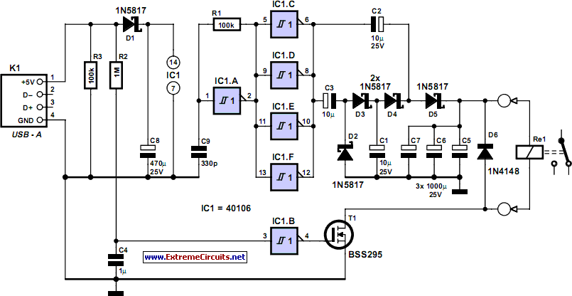
How often does it happen that a user closes down Windows and then forgets to turn off the computer? This circuit addresses that issue by automatically powering off the computer after Windows has been shut down.
This circuit operates by monitoring...

heads or tails
The switch must be a push-to-make, release-to-break type.
An effective circuit utilizing a push-to-make, release-to-break switch can be designed for various applications, particularly in control systems where momentary activation is required. This type of switch, often referred to as a momentary...

DUM23-48 300II AC power distribution unit electrical schematic diagram
The OBO V20C functions as a lightning protection module, capable of handling a maximum lightning damage current of 40 kA. It includes a relay (k), a contactor (KM), a fuse (FU), and traffic lights (HL).
The OBO V20C lightning protection module...
Ac-power-line-connections-monitor
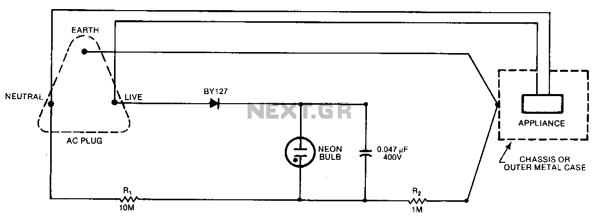
A continuous glow signifies that everything is normal; a blinking or extinguished neon bulb indicates a broken earth or ground connection, or interchanged neutral and live wires.
In electronic circuits, a neon bulb is often used as an indicator light to...