


double symmetrical power supply
#symmetrical power supply
#rectifier bridge
#transformer
#capacitors
#DC voltage
#electronic circuit
#dual power supply
#center tapped transformer
#voltage regulation
#power electronics

Description: If a double power supply is desired but a center-tapped transformer is unavailable, an electronic circuit can be utilized in the following configuration. This circuit employs a second rectifier bridge connected to the secondary coil of the transformer, utilizing two capacitors (C1 and C2). The DC voltage generated is not in galvanic contact with the terminals of the transformer, where the other bridge rectifier is connected, allowing both voltages to be combined into a symmetric voltage.
To create a double power supply without a center-tapped transformer, the described circuit configuration effectively combines the output from two bridge rectifiers. The primary transformer provides the necessary alternating current (AC) voltage, which is then rectified by the first bridge rectifier. The second bridge rectifier is connected to the secondary winding of the transformer, allowing for the generation of an additional DC voltage.
Capacitors C1 and C2 serve as smoothing components. They are connected in parallel with the outputs of the respective bridge rectifiers. Their role is to filter the rectified voltage, reducing ripple and providing a more stable DC output. The output of the first bridge rectifier can be considered as V1, while the output from the second bridge rectifier is V2.
Since the two outputs are not galvanically connected, they can be summed to create a symmetric voltage output. This means that the output can provide both positive and negative voltages relative to a common ground, which is essential for many applications requiring dual polarity supplies, such as operational amplifiers and analog signal processing circuits.
To ensure proper functionality, it is crucial to select the right specifications for the transformer, rectifiers, and capacitors. The transformer must be rated for the required voltage and current, while the rectifiers should be capable of handling the peak inverse voltage (PIV) and the forward current. The capacitors should be chosen based on the desired ripple voltage and load conditions.
Overall, this configuration allows for a versatile power supply solution, enabling the use of standard transformers to achieve dual voltage outputs without the need for a center-tapped design.If you wish to use a double power supply but don`t have a center trapped transformer you can use an electronic circuit in the following configuration. This electronic circuit uses a second rectifier bridge coupled with secondary coil of the transformer using two capacitors (C1 and C2).
Because the DC voltage produced is not in galvanic contact wit h the terminals of the transformer, where is connected the other one bridge rectifier, both voltages can be combined into a symmetric voltage.
To create a double power supply without a center-tapped transformer, the described circuit configuration effectively combines the output from two bridge rectifiers. The primary transformer provides the necessary alternating current (AC) voltage, which is then rectified by the first bridge rectifier. The second bridge rectifier is connected to the secondary winding of the transformer, allowing for the generation of an additional DC voltage.
Capacitors C1 and C2 serve as smoothing components. They are connected in parallel with the outputs of the respective bridge rectifiers. Their role is to filter the rectified voltage, reducing ripple and providing a more stable DC output. The output of the first bridge rectifier can be considered as V1, while the output from the second bridge rectifier is V2.
Since the two outputs are not galvanically connected, they can be summed to create a symmetric voltage output. This means that the output can provide both positive and negative voltages relative to a common ground, which is essential for many applications requiring dual polarity supplies, such as operational amplifiers and analog signal processing circuits.
To ensure proper functionality, it is crucial to select the right specifications for the transformer, rectifiers, and capacitors. The transformer must be rated for the required voltage and current, while the rectifiers should be capable of handling the peak inverse voltage (PIV) and the forward current. The capacitors should be chosen based on the desired ripple voltage and load conditions.
Overall, this configuration allows for a versatile power supply solution, enabling the use of standard transformers to achieve dual voltage outputs without the need for a center-tapped design.If you wish to use a double power supply but don`t have a center trapped transformer you can use an electronic circuit in the following configuration. This electronic circuit uses a second rectifier bridge coupled with secondary coil of the transformer using two capacitors (C1 and C2).
Because the DC voltage produced is not in galvanic contact wit h the terminals of the transformer, where is connected the other one bridge rectifier, both voltages can be combined into a symmetric voltage.
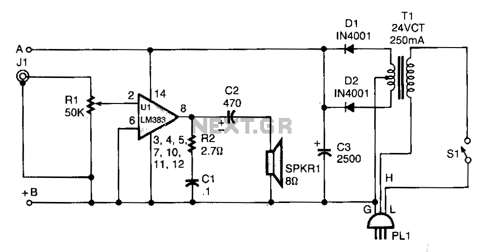
Line-operated-amplifier
T1 isolates the unit from the line and has a 24-V, center-tapped secondary. The output of the transformer is rectified by diodes D1 and D2 and filtered by capacitor C3 to provide 15 to 18 Vdc. The LM383 has built-in...

how does power supply regulate its
Most power supplies regulate either their output voltage or current at a constant level, depending on the load resistance relative to the power supply's output voltage and current settings. This can be summarized as follows: To accomplish this, most power...

Power Supply 0-30V / 0-2A
The basic requirements for a laboratory power supply are to provide the necessary voltages and currents with low output resistance, low noise, minimal ripple, and good stabilization. These requirements are addressed within the circuit design. Many power supplies incorporate electronic...

5v dual power supply
The circuit employs a center-tapped transformer that steps down 230V AC or 110V AC to 9V-0-9V. Four 1N4001 diodes are utilized for the rectification of the AC voltage to DC. A 2200μF / 25V electrolytic capacitor is included to filter...

Voltage Regulator
Neither term describes a regulator, only its placement within a circuit or system. Any voltage regulator could meet the requirements, depending on its placement. A listing of Analog Voltage Regulator IC manufacturers. The types of products or devices they produce...

Car battery charging circuit diagram
The circuit operates on the principle of a transformer, bridge rectifier, and conditioning for battery charging. The charging current can be adjusted to approximately 12V at 100A. For battery charging, a charging rate of 10 hours requires a charging current...
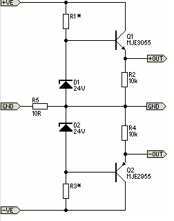
Simple Pre-Regulator
There will be many occasions when it is beneficial to utilize the P05 supply module sourced from a higher voltage supply. For instance, this could be advantageous when integrating balanced inputs.
The P05 supply module is designed to facilitate the conversion...

Classic car battery charging circuit diagram
The circuit operates after a transformer, utilizing a bridge rectifier and conditioning for battery charging. The charging current transformer can be easily adjusted to provide approximately 12V at 100Ah battery charging. The required charging current is 10A, and a 150VA...

40V dual power supply
This 40V dual power supply circuit was designed to power a 150 Watt amplifier circuit. The transformer T1 steps down the mains voltage, while bridge D1 performs rectification. Capacitors C1 and C2 act as filters, and C3 and C4 serve...