


dual power supply with soft power switch
#soft power switch
#transformer
#relay
#Zener diode
#voltage regulation
#current control
#primary circuit
#power management
#resistor network
#delay circuit
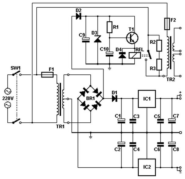
Description: Soft power for a large transformer is implemented by using a series resistance of 100 ohms at 10 watts, or alternatively, two resistors of 47 ohms at 5 watts each in the primary circuit. The resistance is bypassed by a relay after approximately 1.5 seconds, preventing a sudden surge of current during power-up. A Zener diode can be adjusted to accommodate various voltage relays. The schematic diagram originates from a circuit related to a dual power supply with a soft power switch. Further details can be found on the related page discussing the power supply circuit diagram.
The described soft power circuit is designed to manage the inrush current that occurs when a large transformer is energized. Inrush current can lead to potential damage to components and cause circuit instability. By incorporating a series resistor of 100 ohms, or two 47-ohm resistors in parallel, the circuit limits the initial current flow, allowing for a gradual increase in voltage across the transformer. This method enhances the longevity and reliability of the transformer and associated components.
The relay plays a critical role in the operation of this soft power circuit. After a predetermined delay of approximately 1.5 seconds, the relay activates and shorts the series resistance. This transition allows the transformer to operate under normal conditions without the resistive drop, thus improving efficiency. The use of a Zener diode in the circuit provides versatility, as it can be set to accommodate different voltage levels for various relay types. This adjustability ensures compatibility with a range of transformers and power supply configurations.
The dual power supply with a soft power switch design further enhances the functionality of the circuit by allowing for controlled power delivery to multiple outputs. This design is particularly beneficial in applications requiring stable voltage levels and minimal electrical noise, making it suitable for sensitive electronic devices and systems. The schematic diagram associated with this power supply circuit provides a visual representation of the components and their interconnections, aiding in both understanding and implementation.Soft power for a large transformer is made by taking the series resistance of 100 ohms/10 watt or two resistors 47 ohm / 5 watts in the primary circuit, the resistance is shorted by the relay after ± 1. 5 seconds. This avoids a sudden use of the current during power up. A Zener diode can be adjusted to allow theuse of various voltage relay. The schematic diagram come from circuit: Dual Power Supply with Soft Power Switch power supply. Go to that page to read the explanation about above power supply related circuit diagram.
The described soft power circuit is designed to manage the inrush current that occurs when a large transformer is energized. Inrush current can lead to potential damage to components and cause circuit instability. By incorporating a series resistor of 100 ohms, or two 47-ohm resistors in parallel, the circuit limits the initial current flow, allowing for a gradual increase in voltage across the transformer. This method enhances the longevity and reliability of the transformer and associated components.
The relay plays a critical role in the operation of this soft power circuit. After a predetermined delay of approximately 1.5 seconds, the relay activates and shorts the series resistance. This transition allows the transformer to operate under normal conditions without the resistive drop, thus improving efficiency. The use of a Zener diode in the circuit provides versatility, as it can be set to accommodate different voltage levels for various relay types. This adjustability ensures compatibility with a range of transformers and power supply configurations.
The dual power supply with a soft power switch design further enhances the functionality of the circuit by allowing for controlled power delivery to multiple outputs. This design is particularly beneficial in applications requiring stable voltage levels and minimal electrical noise, making it suitable for sensitive electronic devices and systems. The schematic diagram associated with this power supply circuit provides a visual representation of the components and their interconnections, aiding in both understanding and implementation.Soft power for a large transformer is made by taking the series resistance of 100 ohms/10 watt or two resistors 47 ohm / 5 watts in the primary circuit, the resistance is shorted by the relay after ± 1. 5 seconds. This avoids a sudden use of the current during power up. A Zener diode can be adjusted to allow theuse of various voltage relay. The schematic diagram come from circuit: Dual Power Supply with Soft Power Switch power supply. Go to that page to read the explanation about above power supply related circuit diagram.

EI30 Transformer board
Every DAC board and decoder includes a power supply component. The only missing part is the power transformer. A toroidal transformer can be utilized, featuring a power switch and fuse holder mounted on the chassis. This document presents one of...

Common ground for different voltages in relay circuit
The objective is to control a 12 VDC device (on/off) from a microcontroller using a relay card. The relay requires a 12 VDC operating power supply.
To achieve the control of a 12 VDC device using a microcontroller and a relay...

bypass which improves the ability to resist surging of relay contact
During the power-up of the apparatus, the capacitor is primarily responsible for the emergence of surge current. The schematic diagram of the principle is illustrated in Fig. 1. After K1 closes, the capacitor begins to charge, assuming that the direct...

relay triac
The task involves converting a relay in a design to a triac. The circuit switches a 120V nichrome wire with a resistance of 60 ohms. The circuit is powered by a 12V transformer, and there is a 120V neutral and...

Four reversing operation of the reverse brake circuit
The circuit depicted in Figure 3-131 utilizes a relay instead of a speed control relay. It is designed to operate effectively in dusty environments and other challenging conditions.
The circuit operates by employing a relay as a primary switching mechanism, which...

relay interfacing with coolrunner ii cpld
The CoolRunner-II board features external 5V relay interfacing, as indicated in the accompanying figure. The ULN2803 is utilized as a driver for the CPLD I/O lines, with the driver outputs connected to the relay modules. A PTB connector is provided...

Sound-Controlled Relay
This is a relay circuit that detects the presence of sound to activate the relay. This sound-controlled relay can be utilized as a voice-operated switch or for controlling lights.
The sound-activated relay circuit typically employs a microphone or a sound sensor...

Zener Diode checker
Many times we have found itself in the necessity to use a Zener diode and cannot to know the voltage of operation. Many times we cannot read the characteristics or the type that is written on her. In this case,...

An automatic voltage regulator circuit
A step-down transformer converts AC 220V to a lower voltage. A diode bridge rectifier and filter capacitor provide a direct current (DC) output, which fluctuates with variations in the grid voltage. A resistive voltage divider is used for sampling. When...