


Dual Regulated Power Supply
#voltage regulator
#dual power supply
#7815
#7915
#transformer
#bench power supply
#regulated power supply
#positive supply
#negative supply
#18V

Description: The 7815 regulates the positive supply, while the 7915 regulates the negative supply. The transformer should have a primary rating of 240/220 volts for Europe or 120 volts for North America. The center-tapped secondary coil should be rated approximately 18 volts at 1 amp or higher, accommodating losses in the regulator. An application for this type of circuit would be a small regulated bench power supply.
The circuit described utilizes the 7815 and 7915 voltage regulators, which are designed to provide stable output voltages of +15V and -15V, respectively. These regulators are essential components in applications where a dual-polarity power supply is required, such as operational amplifier circuits or analog signal processing.
The transformer is a critical element in this setup. It should be selected based on the geographical voltage supply: either a 240/220V primary for European use or a 120V primary for North American use. The center-tapped secondary coil is designed to deliver approximately 18 volts AC, which is converted to the desired DC output voltage by the regulators. The 1 amp rating of the secondary coil is essential to ensure that there is sufficient current available to meet the demands of the load while also accounting for voltage drops across the regulators.
In the circuit, the output from the center-tapped transformer is fed into the input terminals of the 7815 and 7915 regulators. Each regulator will require appropriate input and output capacitors to stabilize the voltage and filter out any noise. Typically, a 0.33 µF capacitor is placed at the input of each regulator, while a 0.1 µF capacitor is placed at the output to improve transient response and stability.
The output of the 7815 will provide a steady +15V supply, while the output from the 7915 will provide a steady -15V supply. Both outputs can be utilized simultaneously to power various electronic devices that require dual polarity.
To ensure safety and efficiency, it is advisable to incorporate a fuse in the primary circuit to protect against overload conditions. Additionally, heat sinks may be required for the voltage regulators, as they can dissipate significant heat during operation, particularly under high load conditions. The overall design should also consider proper grounding techniques to minimize noise and ensure reliable operation of the power supply circuit.
This configuration is widely used in laboratory settings and for powering low to moderate current electronic projects, making it a versatile solution for various applications in electronics.The 7815 regulatates the positive supply, and the 7915 regulates the negative supply. The transformer should have a primary rating of 240/220 volts for europe, or 120 volts for North America. The centre tapped secondary coil should be rated about 18 volts at 1 amp or higher, allowing for losses in the regulator.
An application for this type of circuit would be for a small regulated bench power supply.
The circuit described utilizes the 7815 and 7915 voltage regulators, which are designed to provide stable output voltages of +15V and -15V, respectively. These regulators are essential components in applications where a dual-polarity power supply is required, such as operational amplifier circuits or analog signal processing.
The transformer is a critical element in this setup. It should be selected based on the geographical voltage supply: either a 240/220V primary for European use or a 120V primary for North American use. The center-tapped secondary coil is designed to deliver approximately 18 volts AC, which is converted to the desired DC output voltage by the regulators. The 1 amp rating of the secondary coil is essential to ensure that there is sufficient current available to meet the demands of the load while also accounting for voltage drops across the regulators.
In the circuit, the output from the center-tapped transformer is fed into the input terminals of the 7815 and 7915 regulators. Each regulator will require appropriate input and output capacitors to stabilize the voltage and filter out any noise. Typically, a 0.33 µF capacitor is placed at the input of each regulator, while a 0.1 µF capacitor is placed at the output to improve transient response and stability.
The output of the 7815 will provide a steady +15V supply, while the output from the 7915 will provide a steady -15V supply. Both outputs can be utilized simultaneously to power various electronic devices that require dual polarity.
To ensure safety and efficiency, it is advisable to incorporate a fuse in the primary circuit to protect against overload conditions. Additionally, heat sinks may be required for the voltage regulators, as they can dissipate significant heat during operation, particularly under high load conditions. The overall design should also consider proper grounding techniques to minimize noise and ensure reliable operation of the power supply circuit.
This configuration is widely used in laboratory settings and for powering low to moderate current electronic projects, making it a versatile solution for various applications in electronics.The 7815 regulatates the positive supply, and the 7915 regulates the negative supply. The transformer should have a primary rating of 240/220 volts for europe, or 120 volts for North America. The centre tapped secondary coil should be rated about 18 volts at 1 amp or higher, allowing for losses in the regulator.
An application for this type of circuit would be for a small regulated bench power supply.

Voltage Regulator Calculation
Before designing an adjustable voltage regulator into a circuit or performing a redesign, it is essential to calculate the values for two resistors. While this calculation is straightforward, locating the appropriate resistors may present challenges. Fortunately, a technique exists to...

2.5V voltage regulator circuit
A 2.5V voltage regulator circuit is illustrated, which is part of a computer's motherboard. The circuit employs an oscillation circuit with the RT9202 control core chip, converting a 5V input supply into a regulated +2.5V output voltage, with the chip's...

LM7805 + 5V power supply configuration
The circuit illustrated in the figure provides an output voltage of +5V and an output current of 1.5A. It comprises a power transformer, a bridge rectifier circuit consisting of diodes D1 to D4, and filter capacitor C1. Additionally, capacitors C2...

transformer Low voltage oscillator for joule thief
A transformer with two input leads and three output leads was used. An LED was connected to two of the output leads, and when a dead AA battery was connected to the input leads, the LED blinked for a brief...
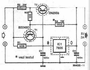
5 volts high current power supply using 7805 voltage regulator
This power supply circuit is designed to provide a high current 5-volt output using a 7805 voltage regulator along with several standard electronic components. The transistor T1 functions as a current limiter. When the voltage across resistors R2 and R3...

a current limiting bench power supply
This is a 1-amp variable-voltage power supply unit (PSU) that can adjust the output voltage from approximately 3V to 24V. It includes a feature that allows for the limitation of the maximum output current, which is particularly useful when powering...

12 Volt 30 Amp Power Supply
This power supply utilizes a single 7812 integrated circuit (IC) voltage regulator in conjunction with multiple external pass transistors to provide output load currents of up to 30 amps.
The circuit design incorporates a 7812 voltage regulator, which is known for...

DIY Satellite Finder Circuit
A circuit has been identified that integrates a voltage regulator and filter to isolate the voltage supplied by the receiver for powering an operational amplifier (op-amp) that drives a meter. Additionally, the circuit isolates the carrier frequency from the satellite,...

kermit
The neighbor's drill charger ceased functioning, and it was discovered that the primary wires in the transformer were defective. The charger featured a straightforward design, comprising a transformer, a diode bridge, and a larger resistor. It was rated to deliver...