


Expanding schematic circuit secondary circuit high-voltage lines
#high-voltage
#schematic
#secondary circuit
#power distribution
#electrical engineering
#circuit expansion
#voltage lines
#transformer
#energy circuits
#wiring

Description: Expanding schematic circuit for the secondary circuit of high-voltage lines.
The schematic circuit for the secondary circuit of high-voltage lines is designed to enhance the distribution and management of electrical power in high-voltage systems. This circuit typically includes components such as transformers, circuit breakers, fuses, and protective relays, which are essential for ensuring safe and efficient operation.
The primary function of the secondary circuit is to step down high voltage to a more manageable level for distribution to various loads. This is achieved through the use of transformers, which convert high-voltage electricity into lower voltage levels suitable for residential or industrial applications. The schematic should clearly indicate the primary and secondary windings of the transformer, along with their respective voltage ratings.
Incorporating circuit breakers within the schematic is crucial for protecting the circuit from overloads and short circuits. These devices are designed to interrupt the circuit in case of fault conditions, thereby preventing damage to equipment and ensuring safety. The schematic should specify the ratings of the circuit breakers in terms of current and voltage.
Fuses may also be included in the design as an additional layer of protection. They serve to disconnect the circuit when excessive current flows through, thereby safeguarding downstream equipment. The type and rating of the fuses should be clearly indicated in the schematic.
Protective relays play a vital role in monitoring the system's operational parameters. They detect abnormal conditions such as overcurrent, overvoltage, or frequency deviations, and initiate protective actions such as tripping circuit breakers. The schematic should detail the configuration of these relays and their connection to the circuit.
Overall, the schematic for the secondary circuit of high-voltage lines must be meticulously designed to ensure clarity and functionality. It should include all necessary components, their ratings, and interconnections to facilitate effective troubleshooting and maintenance. Proper labeling and organization of the schematic will aid in understanding the flow of electricity and the operation of protective devices within the circuit.Expanding schematic circuit secondary circuit high-voltage lines
The schematic circuit for the secondary circuit of high-voltage lines is designed to enhance the distribution and management of electrical power in high-voltage systems. This circuit typically includes components such as transformers, circuit breakers, fuses, and protective relays, which are essential for ensuring safe and efficient operation.
The primary function of the secondary circuit is to step down high voltage to a more manageable level for distribution to various loads. This is achieved through the use of transformers, which convert high-voltage electricity into lower voltage levels suitable for residential or industrial applications. The schematic should clearly indicate the primary and secondary windings of the transformer, along with their respective voltage ratings.
Incorporating circuit breakers within the schematic is crucial for protecting the circuit from overloads and short circuits. These devices are designed to interrupt the circuit in case of fault conditions, thereby preventing damage to equipment and ensuring safety. The schematic should specify the ratings of the circuit breakers in terms of current and voltage.
Fuses may also be included in the design as an additional layer of protection. They serve to disconnect the circuit when excessive current flows through, thereby safeguarding downstream equipment. The type and rating of the fuses should be clearly indicated in the schematic.
Protective relays play a vital role in monitoring the system's operational parameters. They detect abnormal conditions such as overcurrent, overvoltage, or frequency deviations, and initiate protective actions such as tripping circuit breakers. The schematic should detail the configuration of these relays and their connection to the circuit.
Overall, the schematic for the secondary circuit of high-voltage lines must be meticulously designed to ensure clarity and functionality. It should include all necessary components, their ratings, and interconnections to facilitate effective troubleshooting and maintenance. Proper labeling and organization of the schematic will aid in understanding the flow of electricity and the operation of protective devices within the circuit.Expanding schematic circuit secondary circuit high-voltage lines

CENTER TAPPED TRANSFORMER AUDIO OSCILLATOR
The oscillator circuit employs a center-tapped transistor output transformer that functions as a load for the collector of Q1, provides a feedback signal to the base, and acts as the output winding to drive the speaker. Resistor R1 supplies DC...

Neon high-voltage power supply circuit diagram
The neon voltage power supply circuit is straightforward to construct, offering stable output power and other desirable characteristics. The core component of this circuit is the NE555 timer, which generates a high-frequency oscillation signal in the range of 15 to...
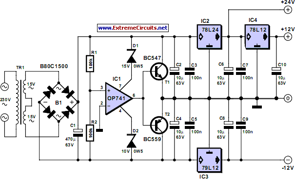
Triple Power Supply
Inexpensive miniature transformers typically provide one or two secondary voltages, which are sufficient for generating a set of positive and negative supply voltages, as required for operational amplifier circuits. However, if an additional voltage higher than either of the supply...
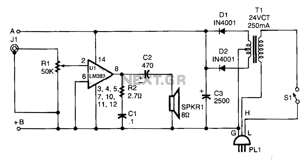
Line-operated-amplifier
T1 isolates the unit from the line and has a 24-V, center-tapped secondary. The output of the transformer is rectified by diodes D1 and D2 and filtered by capacitor C3 to provide 15 to 18 Vdc. The LM383 has built-in...

Series DC power supply
A power supply typically consists of a transformer, rectifier, filter, adjustment components, and reference power supply and sampling circuits. Additionally, it may include overload or short circuit protection devices. The circuit begins with a 220V step-down transformer (T) that converts...

PF Test Equipment
A transformer ratio-arm bridge circuit is utilized as depicted in the simplified diagram of Figure 1. The circuit comprises a standard reference capacitor (CS) and the insulation under test (CX). A distinctive feature of the circuit is a specialized multi-winding...

Classic car battery charging circuit diagram
The circuit operates after a transformer, utilizing a bridge rectifier and conditioning for battery charging. The charging current transformer can be easily adjusted to provide approximately 12V at 100Ah battery charging. The required charging current is 10A, and a 150VA...

Positive High-Voltage Hot Swap Controller with Power Limiter
This is a positive high-voltage hot swap controller circuit with a power limiter. This circuit utilizes the TPS2491 or TPS2490, as both of them have specific features.
The positive high-voltage hot swap controller circuit is designed to safely connect and disconnect...
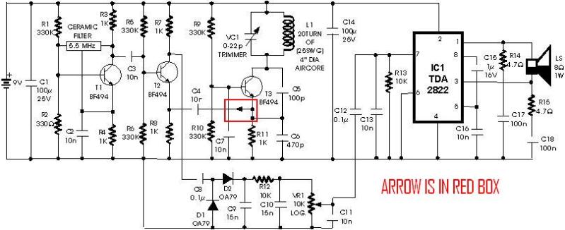
metal detector project circuit
A schematic diagram for a metal detector has been found. The project does not need to be original and can be sourced from the internet. There are several questions regarding this schematic. One query pertains to a small arrow connected...