


Get Negative Rail With Cmos Gates

Description: This circuit utilizes a charge pump and an oscillator operating at 7 kHz. When the clock signal is high, capacitors C and D are activated, grounding the positive side of capacitor CI and providing a negative voltage at the Vs terminal of U2. The output ripple, calculated using capacitors C, CI, and C2, is peak-to-peak. The converter has an output impedance of approximately 100 ohms and can deliver a maximum current of 10 mA DC.
The described circuit employs a charge pump configuration, which is a type of DC-DC converter that generates a higher or lower voltage from a given input voltage by utilizing capacitors to store and transfer charge. The 7 kHz oscillator serves as the driving clock signal that controls the switching of the charge pump circuit.
When the oscillator output is high, capacitors C and D are connected in such a way that capacitor CI is grounded on its positive terminal. This action allows the circuit to create a negative voltage at the Vs terminal of U2, which can be used for various applications requiring a negative supply voltage.
The output ripple, which is an important parameter in power supply design, depends on the values of capacitors C, CI, and C2. The peak-to-peak ripple voltage can be calculated based on the switching frequency and the load current, ensuring that the output remains stable under varying load conditions.
The output impedance of the converter is approximately 100 ohms, indicating that it can effectively drive loads without significant voltage drop under normal operating conditions. The maximum current output capability is specified at 10 mA DC, making this circuit suitable for low-power applications where a negative voltage is required.
Overall, this circuit design is efficient for generating a negative voltage supply from a positive voltage source, and its performance can be optimized by selecting appropriate capacitor values and ensuring that the oscillator operates reliably at the specified frequency. Using a charge pump and oscillator, this circuit uses a 7-kHz oscillator. When the clock is high, C and D are on, grounding the positive side of CI and making negative voltage available at the Vs$ terminal of U2. With C— Ci + C2, the p-p output ripple is: Converter output impedance is about 100 and maximum current is 10 mA dc.
The described circuit employs a charge pump configuration, which is a type of DC-DC converter that generates a higher or lower voltage from a given input voltage by utilizing capacitors to store and transfer charge. The 7 kHz oscillator serves as the driving clock signal that controls the switching of the charge pump circuit.
When the oscillator output is high, capacitors C and D are connected in such a way that capacitor CI is grounded on its positive terminal. This action allows the circuit to create a negative voltage at the Vs terminal of U2, which can be used for various applications requiring a negative supply voltage.
The output ripple, which is an important parameter in power supply design, depends on the values of capacitors C, CI, and C2. The peak-to-peak ripple voltage can be calculated based on the switching frequency and the load current, ensuring that the output remains stable under varying load conditions.
The output impedance of the converter is approximately 100 ohms, indicating that it can effectively drive loads without significant voltage drop under normal operating conditions. The maximum current output capability is specified at 10 mA DC, making this circuit suitable for low-power applications where a negative voltage is required.
Overall, this circuit design is efficient for generating a negative voltage supply from a positive voltage source, and its performance can be optimized by selecting appropriate capacitor values and ensuring that the oscillator operates reliably at the specified frequency. Using a charge pump and oscillator, this circuit uses a 7-kHz oscillator. When the clock is high, C and D are on, grounding the positive side of CI and making negative voltage available at the Vs$ terminal of U2. With C— Ci + C2, the p-p output ripple is: Converter output impedance is about 100 and maximum current is 10 mA dc.

Electronic potentiometer schematic
Electronic potentiometer using a standard CMOS logic and analog multiplexers. Pot have low distortion (0.005% less at 1 V rms) and is it easy for beginners to understand. In the beginning, the art of Hi-Fi, in the absence of high-quality...

Dualxed cmos flasher
Inverters IC1-a and IC1-b form a multivibrator, while IC1-c acts as a buffer. Inverter IC1-d is configured such that its output is the inverse of IC1-c; when pin 6 is high, pin 8 is low, and vice versa. As pins...

Positive-input-negative-output-charge-pump
A charge pump is a straightforward method for generating a low-power voltage supply of opposite polarity from the main supply. The 74CL4 IC serves as a self-oscillating driver for the MOSFET power switch, producing a pulse width of 6.5 microseconds...

Cmos touch switch
This touch switch does not rely on mains hum for switching; it can be used with battery-powered circuits. The Schmitt trigger IC1 forms a 100 kHz oscillator, and IC2a, which is biased into the linear region, amplifies the output and...
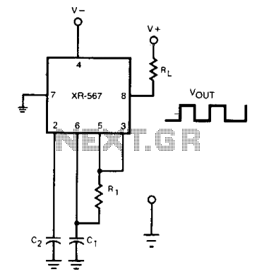
Oscillator with frequency doubled output
The frequency of the current-controlled oscillator can be doubled by feeding a portion of the square-wave output from pin 5 back to the input at pin 3. This configuration allows the quadrature detector to operate as a frequency doubler, resulting...

Cmos-oscillator
The common clock oscillator illustrated in Fig. 68-19A has two minor issues: it may not oscillate if the transition regions of its two gates differ. If it does oscillate, it might occasionally operate at a slightly lower frequency than predicted...

Metal detector circuit diagram 3
The metal detector consists of a probe oscillator, a reference oscillator, an audio amplifier, and various other components, as illustrated in the schematic. The probe oscillator is made up of transistors V1 and V2, a detection coil L1, a capacitor...
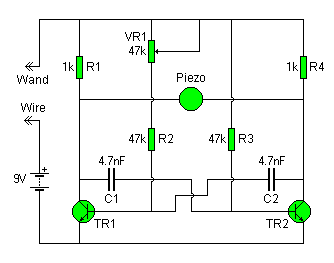
wonky wire
The Wonky Wire circuit is based on the same oscillator used for the Flashing LED Lights. The timing components (R1/C1 and R4/C2) are significantly smaller, resulting in a higher oscillation frequency of approximately 3 kHz (3000 cycles per second). A...

MICROPOWER METAL DETECTOR
This battery-powered metal detector utilizes four exclusive-OR gates found in the 4030 CMOS integrated circuit. The gates are configured as twin oscillators, with a search coil acting as the inductance element in one of the oscillators. When the coil approaches...