


Inverting Power Supply Circuit
#inverting
#negative voltage
#dc voltage
#power supply
#voltage converter
#voltage regulation
#electronics
#circuit design

Description: This circuit will provide a negative DC voltage that is approximately equal to the positive input voltage at no load and about 3 V less at a 10 mA load. The input voltage range is from +5 to +15 V DC. It is important not to exceed 15 V to prevent potential damage to the circuit.
The circuit in question is designed to generate a negative DC voltage output from a positive DC voltage input. The operation is based on the principle of voltage inversion, typically achieved through the use of an operational amplifier (op-amp) in an inverting configuration or through specialized voltage inverter circuits.
At no load conditions, the output voltage closely mirrors the magnitude of the input voltage, providing a user-friendly interface for applications requiring a negative voltage reference. However, as the load increases, specifically at a 10 mA load, the output voltage decreases by approximately 3 V. This drop in voltage is an important consideration for applications that require stable output under varying load conditions.
The input voltage range is specified between +5 V and +15 V DC, which sets the operational limits for the circuit. It is crucial to adhere to this voltage range to avoid damaging sensitive components within the circuit, particularly the operational amplifier or any voltage regulator used. Exceeding the maximum input voltage of 15 V could lead to catastrophic failure, hence the need for protective measures such as voltage clamping or current limiting.
In practical implementations, additional components such as capacitors may be included to stabilize the output voltage and filter any noise present in the input signal. Diodes can also be utilized to prevent reverse voltage conditions that could damage the circuit. Proper thermal management should be considered, especially when the circuit operates near its maximum ratings, to ensure longevity and reliability.
Overall, this circuit serves a critical role in applications requiring a negative voltage supply, with careful attention to input limits and load conditions to ensure optimal performance and prevent damage. This circuit will provide a negative dc voltage that is approximately equal to the positive input voltage at no load and about 3 V less at 10 mA load. -`~ is from +5 to +15 Vdc. Do not exceed 15 V or Ul might be damaged.
The circuit in question is designed to generate a negative DC voltage output from a positive DC voltage input. The operation is based on the principle of voltage inversion, typically achieved through the use of an operational amplifier (op-amp) in an inverting configuration or through specialized voltage inverter circuits.
At no load conditions, the output voltage closely mirrors the magnitude of the input voltage, providing a user-friendly interface for applications requiring a negative voltage reference. However, as the load increases, specifically at a 10 mA load, the output voltage decreases by approximately 3 V. This drop in voltage is an important consideration for applications that require stable output under varying load conditions.
The input voltage range is specified between +5 V and +15 V DC, which sets the operational limits for the circuit. It is crucial to adhere to this voltage range to avoid damaging sensitive components within the circuit, particularly the operational amplifier or any voltage regulator used. Exceeding the maximum input voltage of 15 V could lead to catastrophic failure, hence the need for protective measures such as voltage clamping or current limiting.
In practical implementations, additional components such as capacitors may be included to stabilize the output voltage and filter any noise present in the input signal. Diodes can also be utilized to prevent reverse voltage conditions that could damage the circuit. Proper thermal management should be considered, especially when the circuit operates near its maximum ratings, to ensure longevity and reliability.
Overall, this circuit serves a critical role in applications requiring a negative voltage supply, with careful attention to input limits and load conditions to ensure optimal performance and prevent damage. This circuit will provide a negative dc voltage that is approximately equal to the positive input voltage at no load and about 3 V less at 10 mA load. -`~ is from +5 to +15 Vdc. Do not exceed 15 V or Ul might be damaged.

Lighting controller circuit
The circuit operates with a controller that includes a power supply circuit, a control circuit, and an audio amplifier, which are three distinct components. The power circuit comprises diodes VD1 to VD4, resistor R1, capacitor C1, LED1, LED2, and additional...

12v to 220v converter circuit
This DIY 12V to 220V voltage converter is built with a CMOS 4047, which serves as the main component of this compact voltage converter that transforms 12V DC into 220V AC. The 4047 functions as an astable multivibrator; at pins...

12v to 3v converter
This document presents a straightforward and practical schematic for a 12V to 3V converter circuit. The output current of the circuit is approximately 1A.
The 12V to 3V converter circuit is typically designed using a linear voltage regulator or a buck...

30V from 5V converter
I made the power supply which makes about +30V with +5V power supply. The direct current is changed into the alternating current by the oscillator which used the schmitt trigger inverter which has the hysteresis characteristic and the resonance circuit....
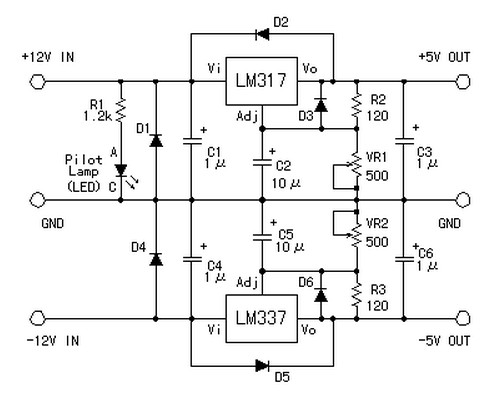
symmetric 12v to 5v converter
Symmetric 12V to 5V converter power supply. Refer to the designated page for an explanation regarding the associated circuit diagram.
The symmetric 12V to 5V converter power supply is designed to efficiently step down a 12V input voltage to a regulated...

Simple-power-supply
This power supply provides both +9 V and -9 V outputs to replace two 9-V batteries. The rectifier circuit consists of two separate full-wave rectifiers, each connected to the secondary winding of the transformer. The first full-wave rectifier, made up...

Regulator circuit silicon resistor formed
The simple voltage regulator circuit consists of a silicon regulator and a resistor. It is designed to rectify and filter DC voltage, as illustrated in the accompanying figure. The voltage regulator is connected in parallel with the load, and the...

5V From 4Aa Cells Circuit
This unique logic-power-converter design allows for a switchable output of 3.6 V or 5 V at 200 mA using four AA cells. The supply features a MOSFET switch that can connect to a lithium backup battery, providing a 3.4 V...

Voltage Regulator
Neither term describes a regulator, only its placement within a circuit or system. Any voltage regulator could meet the requirements, depending on its placement. A listing of Analog Voltage Regulator IC manufacturers. The types of products or devices they produce...