


ISO103 ripple reduction circuit diagram
#ripple reduction
#RC filter
#high-pass filter
#ISO103
#output filtering
#circuit design
#power management
#voltage regulation
#filtering
#DC current

Description: The ISO103 ripple reduction circuit features an output circuit combined with an RC high-pass filter designed to filter out output ripple without impacting the direct current (DC) characteristics. Under specific conditions, the circuit is capable of reducing an 800 kHz ripple voltage to 5 mVp-p.
The ISO103 is a precision instrumentation amplifier that is often utilized in applications requiring low noise and high accuracy. The ripple reduction circuit is particularly crucial in scenarios where power supply noise can adversely affect signal integrity. The incorporation of an RC high-pass filter serves to eliminate unwanted AC ripple components from the output while maintaining the DC level.
The circuit typically consists of a resistor (R) and a capacitor (C) arranged in series, with the output taken across the capacitor. The values of R and C are chosen based on the desired cutoff frequency, which is calculated using the formula:
\[ f_c = \frac{1}{2\pi RC} \]
where \( f_c \) is the cutoff frequency. For an 800 kHz ripple voltage, the filter must be designed to effectively attenuate frequencies around this value while allowing the DC component to pass through with minimal attenuation.
In practical applications, the selection of R and C will depend on the load conditions and the acceptable ripple voltage at the output. Careful consideration is required to ensure that the RC time constant is appropriate for the expected signal dynamics. The performance of the circuit can be further optimized by selecting components with low tolerances and temperature coefficients to ensure stability over varying operating conditions.
Overall, the ISO103 ripple reduction circuit with an RC high-pass filter is an effective solution for minimizing ripple voltage in sensitive electronic applications, ensuring that the DC output remains stable and reliable. As shown for the ISO103 ripple reduction circuit. Circuit at the output plus an RC high-pass filter for filtering output ripple bang, without affecting the current (DC) feature conditions 800kHz ripple voltage can be reduced to 5mVp-p.
The ISO103 is a precision instrumentation amplifier that is often utilized in applications requiring low noise and high accuracy. The ripple reduction circuit is particularly crucial in scenarios where power supply noise can adversely affect signal integrity. The incorporation of an RC high-pass filter serves to eliminate unwanted AC ripple components from the output while maintaining the DC level.
The circuit typically consists of a resistor (R) and a capacitor (C) arranged in series, with the output taken across the capacitor. The values of R and C are chosen based on the desired cutoff frequency, which is calculated using the formula:
\[ f_c = \frac{1}{2\pi RC} \]
where \( f_c \) is the cutoff frequency. For an 800 kHz ripple voltage, the filter must be designed to effectively attenuate frequencies around this value while allowing the DC component to pass through with minimal attenuation.
In practical applications, the selection of R and C will depend on the load conditions and the acceptable ripple voltage at the output. Careful consideration is required to ensure that the RC time constant is appropriate for the expected signal dynamics. The performance of the circuit can be further optimized by selecting components with low tolerances and temperature coefficients to ensure stability over varying operating conditions.
Overall, the ISO103 ripple reduction circuit with an RC high-pass filter is an effective solution for minimizing ripple voltage in sensitive electronic applications, ensuring that the DC output remains stable and reliable. As shown for the ISO103 ripple reduction circuit. Circuit at the output plus an RC high-pass filter for filtering output ripple bang, without affecting the current (DC) feature conditions 800kHz ripple voltage can be reduced to 5mVp-p.

A Power Management Interface Circuit For Telecom Hot Swap With Local Dc/dc Conve
New cellular phones have incorporated high-resolution cameras that require bright illumination of the surrounding area to achieve high-quality pictures. Traditional xenon-filled photo flashes cannot be used due to the limited space available in cellular phone cameras. Instead, design engineers utilize...

variable voltage and current power supply
An alternative method for utilizing operational amplifiers (op-amps) to regulate a power supply is illustrated below. The power transformer necessitates an additional winding to provide the op-amps with a bipolar voltage of +/- 8 volts. This negative voltage is also...

Voltage Regulators
Until Willow Garage was acquired, there was work as a Web Robotics Engineer. This title reflects a role as a full-stack engineer focused on real-time, distributed robot control. Notable projects include an XML-RPC server and client for Node.js, a deprecated...

RC filters-operation-circuit-diagram
The disadvantages of pi-filters include higher costs, increased weight, larger size, and the external magnetic field generated by the series inductor. These issues can be mitigated by substituting the series inductor with a series resistor, referred to as an R-C...
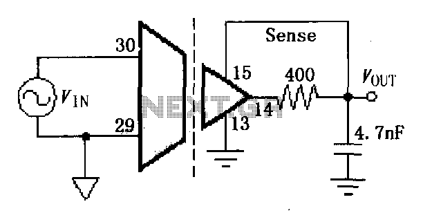
ISO107 ripple reduction circuit
The ISO107 ripple reduction circuit includes an RC high-pass filter at the output to filter the output voltage ripple without impacting the DC characteristics. This configuration allows for a reduction of the 800kHz ripple voltage to less than 3mVp-p.
The ISO107...
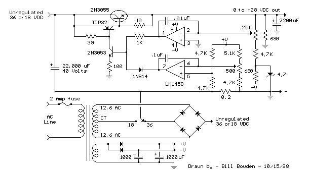
Current and Variable Voltage Power Supply
Another adjustment of application operational amplifiers to adapt a power supply is apparent below. The power supply requires an additional adjustment to supply the op-amps with a bipolar voltage (+/- 8 volts), and the negative voltage is also used to...

Bridge voltage regulator circuit diagram using the
The circuit depicted in Figures A, B, and C demonstrates a high voltage coefficient. When the regulator resistance \( r_z \) is held constant, the bridge configuration achieves an infinite voltage coefficient. In Figure A, the load circuit is connected...

Design and making of the stabilized voltage supply of switch
Under the loading condition of the resistance, the output voltage (Uo) variable range is from 30V to 36V, with a maximum output current (Imax) of 2A. When the input voltage (U2) changes from 15V to 21V, the voltage regulation factor...
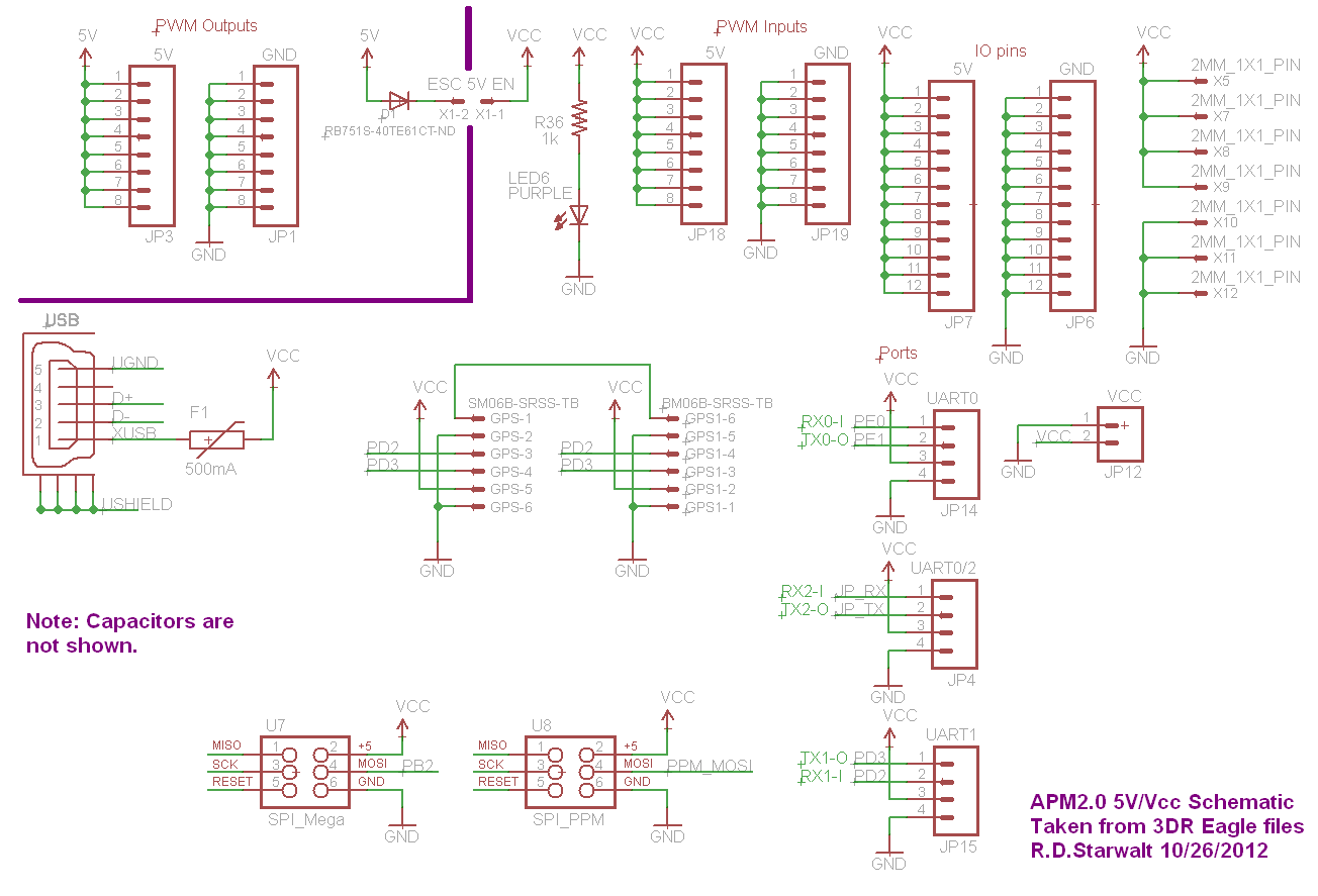
APM2.0 5V/Vcc Schematic
The PWM Output section has been separated into the upper left corner, delineated by a heavy purple line that is bridged by jumper JP1 on the APM2.0. This design choice highlights that diode D1 allows current to pass through JP1,...