


LM2576T IC Step-Down Switching Power Supply
#LM2576T
#step-down
#switching
#voltage regulator
#60V input
#3.3V output
#5V output
#12V output
#15V output
#power supply circuit

Description: This circuit illustrates the LM2576T integrated circuit (IC) step-down switching power supply circuit diagram. Features include a 60V input voltage with output options of 3.3V, 5V, 12V, and 15V.
The LM2576T is a popular voltage regulator known for its ability to efficiently convert a higher input voltage to a lower output voltage, making it suitable for various applications requiring power regulation. The circuit typically comprises an LM2576T IC, which is designed to handle input voltages up to 60V and can deliver a maximum output current of 3A.
The schematic includes several key components:
1. **Input Capacitor (C1)**: This capacitor filters the input voltage and stabilizes it before it reaches the LM2576T. A value of 100µF is commonly used to ensure adequate filtering, which helps to reduce voltage spikes that could damage the IC.
2. **Inductor (L1)**: The inductor is crucial for energy storage in the switching process. It allows the circuit to maintain a steady output voltage by storing energy when the switch is closed and releasing it when the switch is open. The inductance value is typically in the range of 33µH to 100µH, depending on the desired output voltage and current.
3. **Diode (D1)**: A Schottky diode is often employed in this circuit configuration due to its fast switching capability and low forward voltage drop. This diode is positioned in parallel with the load and is essential for allowing current to flow back to the output when the inductor discharges.
4. **Output Capacitor (C2)**: This capacitor smooths out the output voltage and reduces ripple. A value of 220µF is commonly used to ensure that the output remains stable under varying load conditions.
5. **Feedback Resistors (R1 and R2)**: These resistors form a voltage divider that provides feedback to the LM2576T, allowing it to regulate the output voltage accurately. The resistor values can be selected based on the desired output voltage.
6. **Additional Components**: Depending on the application, additional capacitors and resistors may be included to further stabilize the circuit and improve transient response.
This configuration is versatile, allowing for adjustments to meet specific voltage requirements. The LM2576T's built-in thermal shutdown and current limiting features enhance the circuit's reliability, making it suitable for a wide range of electronic devices and systems.This circuit shows about LM2576T IC Step-Down Switching Power Supply Circuit Diagram. Features:60V input voltage, 3.3 V/5V/12V/15V output ..
The LM2576T is a popular voltage regulator known for its ability to efficiently convert a higher input voltage to a lower output voltage, making it suitable for various applications requiring power regulation. The circuit typically comprises an LM2576T IC, which is designed to handle input voltages up to 60V and can deliver a maximum output current of 3A.
The schematic includes several key components:
1. **Input Capacitor (C1)**: This capacitor filters the input voltage and stabilizes it before it reaches the LM2576T. A value of 100µF is commonly used to ensure adequate filtering, which helps to reduce voltage spikes that could damage the IC.
2. **Inductor (L1)**: The inductor is crucial for energy storage in the switching process. It allows the circuit to maintain a steady output voltage by storing energy when the switch is closed and releasing it when the switch is open. The inductance value is typically in the range of 33µH to 100µH, depending on the desired output voltage and current.
3. **Diode (D1)**: A Schottky diode is often employed in this circuit configuration due to its fast switching capability and low forward voltage drop. This diode is positioned in parallel with the load and is essential for allowing current to flow back to the output when the inductor discharges.
4. **Output Capacitor (C2)**: This capacitor smooths out the output voltage and reduces ripple. A value of 220µF is commonly used to ensure that the output remains stable under varying load conditions.
5. **Feedback Resistors (R1 and R2)**: These resistors form a voltage divider that provides feedback to the LM2576T, allowing it to regulate the output voltage accurately. The resistor values can be selected based on the desired output voltage.
6. **Additional Components**: Depending on the application, additional capacitors and resistors may be included to further stabilize the circuit and improve transient response.
This configuration is versatile, allowing for adjustments to meet specific voltage requirements. The LM2576T's built-in thermal shutdown and current limiting features enhance the circuit's reliability, making it suitable for a wide range of electronic devices and systems.This circuit shows about LM2576T IC Step-Down Switching Power Supply Circuit Diagram. Features:60V input voltage, 3.3 V/5V/12V/15V output ..

9 Volt 2 Ampere DC Power Supply Circuit
This circuit primarily relies on a voltage regulator. The 7809 voltage regulator can provide a continuous output of up to 2 amps while ensuring a low noise and highly regulated supply. Although the circuit can function without additional components, a...

Switching Voltage Regulators-Step up Step down and polarity invert
Switching voltage regulators include step-up, step-down, and polarity-inverting configurations, along with their working principles and circuit diagrams.
Switching voltage regulators are essential components in modern electronic circuits, providing efficient voltage conversion. These regulators can be categorized into three main types: step-up...
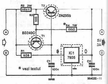
5 volts high current power supply using 7805 voltage regulator
This power supply circuit is designed to provide a high current 5-volt output using a 7805 voltage regulator along with several standard electronic components. The transistor T1 functions as a current limiter. When the voltage across resistors R2 and R3...

Expand integrated three-terminal regulator block circuit output current method
Expand integrated three-terminal regulator block circuit output current method
The integrated three-terminal regulator is a versatile component commonly used in power supply circuits to provide a stable output voltage. This regulator typically consists of three terminals: input, output, and ground. The...

Switching Power Supply
The circuit depicted in the schematic below represents an enhanced generator electronics system. It is an unregulated switcher designed to maximize sound output while ensuring prolonged CPU operation. This circuit efficiently transfers electrical energy from the generator, outperforming traditional rectifier...

12v power supply circuit
This project involves a straightforward and practical 12V power supply circuit utilizing the LM7812 integrated circuit (IC). The LM7812 is a three-terminal fixed voltage regulator IC housed in a TO-220 package. It incorporates several built-in features such as thermal shutdown,...

5v 1a power supply using lm2575
A power transistor with a voltage drop of 4 volts and a current of 3 amps may dissipate approximately 12 watts of heat, presenting a challenge in series regulators. In contrast, a saturated transistor or MOSFET with a voltage drop...

Dual Voltage 12V Power Supply
The following circuit diagram of a dual voltage power supply can be used for miscellaneous applications. It requires a few components to build. The most important components of this circuit are regulators: 1: (AN) 7812 and 2: (AN) 7912. AN7812...

A TREAD sized regulator
The size of the tread was 5 cm by 3 cm. The current design measures 5 cm by 3.3 cm. The regulator's foundation is based on Walt Jung's 1997 article, "Regulator Excels in Noise and Line Rejection," with modifications derived...