


Low-Cost AC Supply
#AC supply
#linear regulator
#rectifier
#filter
#low current
#high voltage
#simple circuit
#electronics
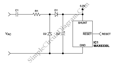
Description: Applying the filtered and rectified AC input to a high-input-voltage linear regulator is the simplest way to produce a low current level from an AC source.
The process of converting an AC source to a low current level using a high-input-voltage linear regulator involves several key steps. Initially, the AC voltage is filtered and rectified to convert it into a usable DC voltage. This is typically accomplished using a combination of diodes and capacitors. The diodes serve to rectify the AC signal, allowing current to flow in only one direction, while the capacitors smooth out the resulting pulsating DC voltage, reducing ripple and providing a more stable output.
Once the AC input has been rectified and filtered, the next stage involves feeding this DC voltage into a high-input-voltage linear regulator. The linear regulator is designed to provide a consistent output voltage, irrespective of variations in input voltage or load conditions. The operation of the linear regulator is based on controlling the voltage drop across a pass element, typically a transistor, which dissipates excess voltage as heat.
The selection of the linear regulator must consider the maximum input voltage, output voltage requirements, and the current rating. The regulator should be chosen to ensure that it can handle the filtered DC voltage without exceeding its maximum input specifications. Additionally, thermal management must be addressed, as linear regulators can generate significant heat, especially when there is a large difference between input and output voltages.
The output from the linear regulator provides a low current level suitable for powering sensitive electronic circuits or components that require stable voltage levels. This setup is particularly advantageous in applications where simplicity and low noise are critical, such as in audio equipment or precision measurement devices. Proper bypass capacitors may also be included at the output to further stabilize the voltage and filter out high-frequency noise.
In summary, the combination of filtering, rectification, and regulation allows for the effective conversion of AC power into a stable low current DC output, making it a fundamental approach in various electronic applications.Applying the filtered and rectified AC input to a high-input-voltage linear regulator is the simplest way to produce low current level from an AC source..
The process of converting an AC source to a low current level using a high-input-voltage linear regulator involves several key steps. Initially, the AC voltage is filtered and rectified to convert it into a usable DC voltage. This is typically accomplished using a combination of diodes and capacitors. The diodes serve to rectify the AC signal, allowing current to flow in only one direction, while the capacitors smooth out the resulting pulsating DC voltage, reducing ripple and providing a more stable output.
Once the AC input has been rectified and filtered, the next stage involves feeding this DC voltage into a high-input-voltage linear regulator. The linear regulator is designed to provide a consistent output voltage, irrespective of variations in input voltage or load conditions. The operation of the linear regulator is based on controlling the voltage drop across a pass element, typically a transistor, which dissipates excess voltage as heat.
The selection of the linear regulator must consider the maximum input voltage, output voltage requirements, and the current rating. The regulator should be chosen to ensure that it can handle the filtered DC voltage without exceeding its maximum input specifications. Additionally, thermal management must be addressed, as linear regulators can generate significant heat, especially when there is a large difference between input and output voltages.
The output from the linear regulator provides a low current level suitable for powering sensitive electronic circuits or components that require stable voltage levels. This setup is particularly advantageous in applications where simplicity and low noise are critical, such as in audio equipment or precision measurement devices. Proper bypass capacitors may also be included at the output to further stabilize the voltage and filter out high-frequency noise.
In summary, the combination of filtering, rectification, and regulation allows for the effective conversion of AC power into a stable low current DC output, making it a fundamental approach in various electronic applications.Applying the filtered and rectified AC input to a high-input-voltage linear regulator is the simplest way to produce low current level from an AC source..

600 VOLTS POWER SUPPLY FOR QRO
Amateur Radio Transmitters using valves such as 807 or 1625 works well with a plate voltage between 600V to 700 Volts. The circuit described here is a full wave voltage doubler. The output voltage is twice the input voltage. For...

High voltage generator circuit
This circuit is highly dangerous due to its output voltage, which is in kilovolts and poses a significant risk of serious injury or death. It should only be attempted by individuals with extensive experience in handling high voltages. No responsibility...
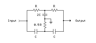
Twin-T RC Notch Filter
The two T-notch filter can be utilized to block unwanted frequencies or, when incorporated into an operational amplifier, function as a bandpass filter. The notch frequency occurs when the capacitive reactance equals the resistance (Xc = R), and if these...

Low Cost High Voltage Power Supply
This high voltage, low current power supply has been designed for various experiments in systems and synthetic biology. The schematic and board layout are provided below. The circuit can output up to +1,866 VDC at under 1 mA and can...

Rejection filter
This narrowband filter utilizing the 741 operational amplifier can achieve a rejection level of up to 60 dB. By employing resistors with a value of 100 K ohms and capacitors of 320 pF, the circuit effectively rejects frequencies at 50...

RC Low-Pass passive Filter
What is the purpose of this circuit? Basically it has two roles: to pass the desired low frequency signals and stop the unwanted high frequency signals. Open the netlist file lpfilter1.cir with your SPICE simulator. Most simulators display the netlist...

marx generator
The spark gap in the initial design consisted of copper wires bent into a ring at the end to suppress corona discharge. The current design is more advanced, utilizing spherical electrodes. This setup generates a 300 kV output pulse with...

Xenon Flasher
This project generates 350V DC and stores the voltage in a large electrolytic capacitor. While this voltage is not lethal, it can deliver a significant shock. This aspect of the project serves an educational purpose, teaching users to handle high-voltage...

Half-wave rectifier
This circuit allows for precise half-wave rectification of the incoming signal. It exhibits a gain of 0 for positive signals and a gain of -1 for negative signals. By reversing the orientation of both diodes, the output polarity can be...