


LT3083 current limiting
#LT3083
#current limiting
#voltage regulator
#analog control
#power supply unit
#transistor
#oscillation
#simulation
#digital readout

Description: The circuit utilizes standard analog control through potentiometers while incorporating digital readouts for voltage and current measurements. Despite reviewing power supply unit (PSU) video tutorials, the single LT308x configuration with a transistor limiter did not function as expected in simulations. Specifically, it failed to reach 0 volts, resulting in excessive current flow (over 2 amps) during output short circuits, and exhibited occasional oscillation issues. Consequently, a decision has been made to pursue a simpler, albeit more costly, approach by employing two LT3083 voltage regulators. An LTSpice circuit has been created, omitting the MAX4080T current sense amplifier, which is stored in a separate file. This omission does not impact the current inquiries. It is important to note that "Iset" and "Vset" are configured as potentiometers functioning as rheostats, modeled as resistors in LTSpice due to the absence of a dedicated potentiometer component. In this configuration, they are driven by a 50 µA current from the LT3083. The intention is to utilize Rlimit (0.5 ohms) as the current sense resistor, employing a 5x gain amplifier to negate the additional 250 mV drop across Rsense at the output. However, challenges arise due to significant ripple between the regulators when current limit mode is inactive; the left LT3083 outputs the maximum voltage, allowing input ripple to pass through unchanged.
The described circuit employs two LT3083 voltage regulators to achieve stable output voltage and current control. The LT3083 is a low-dropout linear voltage regulator known for its high accuracy and low noise, making it suitable for precision applications. The use of analog control through potentiometers for setting current (Iset) and voltage (Vset) allows for fine-tuning of the output parameters, while the digital readouts provide real-time monitoring of the voltage and current levels.
In this configuration, the potentiometers are modeled as resistors in LTSpice simulations to account for the absence of a potentiometer component. Each potentiometer is connected to a 50 µA current source from the LT3083, ensuring that the adjustments made to Iset and Vset are effective and responsive. The choice of a 0.5-ohm resistor as Rlimit serves a dual purpose: it acts as a current sense resistor and facilitates current limiting functionality. By employing a 5x gain amplifier, the design aims to minimize the voltage drop across Rsense, which can otherwise introduce inaccuracies in the output voltage.
The issue of ripple between the regulators when not in current limit mode indicates the need for careful design consideration. The left LT3083's tendency to output maximum voltage can lead to instability and undesirable ripple effects. To mitigate this, additional filtering or feedback mechanisms may be necessary to stabilize the output and reduce the influence of input ripple. This could involve implementing capacitors at the output or utilizing additional components to enhance the regulation performance under varying load conditions.
In summary, the circuit design focuses on achieving precise voltage and current control through the integration of LT3083 regulators, potentiometers for adjustment, and a current sensing mechanism to ensure safe operation. Addressing the ripple issue will be crucial for maintaining stable performance and reliability in the overall system.I`m using regular analog control via pots, though will use digital readouts of voltage/current. Anyhow. I HAVE watched the PSU videos, but at least in simulations I couldn`t get the single-LT308x with the transistor limiter to work properly (one, it didn`t go to 0, so a shorted output causes >2 amps to flow! - and two, it tended to oscillate a bit now and then). I`ve almost decided to go a simpler but more expensive route and simply use two LT3083s. I attached the LTSpice circuit, though without the MAX4080T current sense amp, since that component is in a separate file on my computer. It didn`t affect these questions whatsoever, though. Also, note that "Iset" and "Vset" are potentiometers wired as rheostats; I model them as resistors in LTSpice since there`s no built-in pot component.
In each case, they`re controlled by a 50 µA current from the LT3083. What I`d like to do is to use Rlimit (0. 5 ohms) as the current sense resistor (with a 5x gain amp instead, of course), to eliminate the extra 250 mV drop over Rsense at the output. The reason I "can`t" right now is that there is a lot of ripple between the regulators when the current-limit mode isn`t active; the left LT3083 simply outputs as high a voltage as it can, which lets the input ripple through unchanged:
The described circuit employs two LT3083 voltage regulators to achieve stable output voltage and current control. The LT3083 is a low-dropout linear voltage regulator known for its high accuracy and low noise, making it suitable for precision applications. The use of analog control through potentiometers for setting current (Iset) and voltage (Vset) allows for fine-tuning of the output parameters, while the digital readouts provide real-time monitoring of the voltage and current levels.
In this configuration, the potentiometers are modeled as resistors in LTSpice simulations to account for the absence of a potentiometer component. Each potentiometer is connected to a 50 µA current source from the LT3083, ensuring that the adjustments made to Iset and Vset are effective and responsive. The choice of a 0.5-ohm resistor as Rlimit serves a dual purpose: it acts as a current sense resistor and facilitates current limiting functionality. By employing a 5x gain amplifier, the design aims to minimize the voltage drop across Rsense, which can otherwise introduce inaccuracies in the output voltage.
The issue of ripple between the regulators when not in current limit mode indicates the need for careful design consideration. The left LT3083's tendency to output maximum voltage can lead to instability and undesirable ripple effects. To mitigate this, additional filtering or feedback mechanisms may be necessary to stabilize the output and reduce the influence of input ripple. This could involve implementing capacitors at the output or utilizing additional components to enhance the regulation performance under varying load conditions.
In summary, the circuit design focuses on achieving precise voltage and current control through the integration of LT3083 regulators, potentiometers for adjustment, and a current sensing mechanism to ensure safe operation. Addressing the ripple issue will be crucial for maintaining stable performance and reliability in the overall system.I`m using regular analog control via pots, though will use digital readouts of voltage/current. Anyhow. I HAVE watched the PSU videos, but at least in simulations I couldn`t get the single-LT308x with the transistor limiter to work properly (one, it didn`t go to 0, so a shorted output causes >2 amps to flow! - and two, it tended to oscillate a bit now and then). I`ve almost decided to go a simpler but more expensive route and simply use two LT3083s. I attached the LTSpice circuit, though without the MAX4080T current sense amp, since that component is in a separate file on my computer. It didn`t affect these questions whatsoever, though. Also, note that "Iset" and "Vset" are potentiometers wired as rheostats; I model them as resistors in LTSpice since there`s no built-in pot component.
In each case, they`re controlled by a 50 µA current from the LT3083. What I`d like to do is to use Rlimit (0. 5 ohms) as the current sense resistor (with a 5x gain amp instead, of course), to eliminate the extra 250 mV drop over Rsense at the output. The reason I "can`t" right now is that there is a lot of ripple between the regulators when the current-limit mode isn`t active; the left LT3083 simply outputs as high a voltage as it can, which lets the input ripple through unchanged:

Transistor attenuation - feedback tone circuit
Figure 4-11 illustrates a feedback attenuator that comprises a transistor-based tone control circuit. This circuit features a conventional high and bass control system, along with balance control, volume control, loudness adjustment, and subwoofer control, as well as field sense control....

Simple Metronome using transistor
This circuit is a simple metronome model designed for ease of use. It employs transistors as key components, specifically configured as an astable multivibrator, to produce a beeping sound. The tone can be adjusted using a variable resistor (VR1). A...

DARLINGTON LOGIC PROBE
A two-transistor Darlington connection offers a very high input impedance, ensuring that it does not load the logic circuit being monitored. This configuration drives an LED that illuminates when a logic high (1) is present at the input.
The two-transistor Darlington...

General-purpose-power-supply
The supply 6-66 can be utilized for output voltages ranging from 1 to 35 V. The line transformer must be selected to provide approximately 1.4 times the desired output voltage from the positive side of filter capacitor C1 to ground....
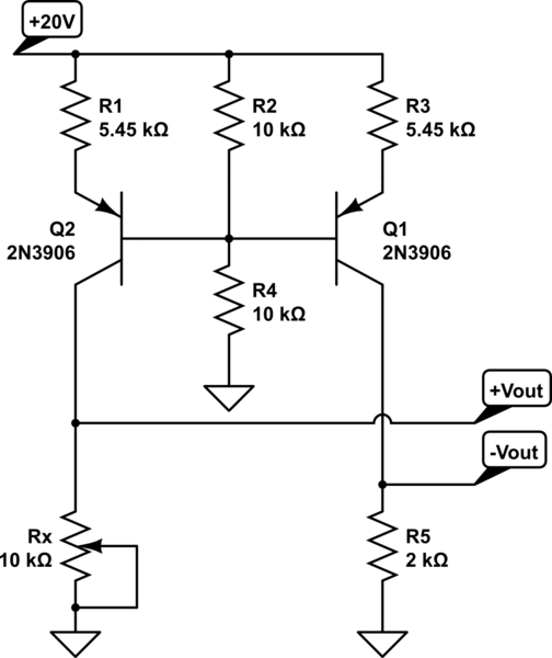
How do you make a shift/scale circuit using a transistor resistors and a voltage source
A functional circuit utilizing an operational amplifier (op-amp); however, the instructor indicated that op-amps can be challenging to work with and provided transistors as an alternative.
Operational amplifiers (op-amps) are versatile components commonly used in various electronic circuits for amplification,...

transistors Controlling LED with 300mV AC signal
Control an LED with an audio signal; however, the output signal is only 150 mV peak-to-peak (with a 150 mV positive offset). It is understood that a higher voltage than 0.6 V is required to activate the transistor, leading to...
lie detector
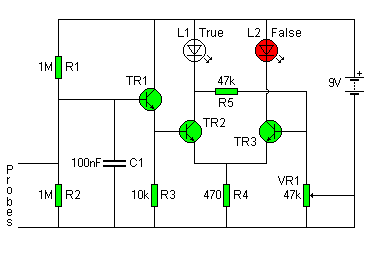
The circuit diagram of the Lie Detector consists of three transistors (TR1 to TR3), a capacitor (C1), two LEDs (L1 & L2), five resistors (R1 to R5), and a variable resistor (VR1). Suitable transistors include BC547, BC548, or BC549, or...

AC arc welding machine transistor load power path from 2
The AC arc welding machine's transistor load path for the power from the second circuit is illustrated. The figure shows a current transformer with a core cross-section of 25 mm². The transformer has a primary winding with a certain number...

Amplifier input signal overdrive auto-protection
That circuit protects the overdriven signals going into an amplifier. Instead of a zener diode, we use a transistor. That way we ensure that the above the ordinary input voltages (1 volt r.m.s.) can be achieved without distortion. Also, the...