


MAKING YOUR OWN REGULATED POWER SUPPLY
#regulated
#power supply
#voltage
#electronics
#DIY
#constant voltage
#circuit
#basic electronics
#project

Description: This document presents a basic electronics project focused on creating a regulated power supply. A regulated power supply is essential for various electronic circuits, as it provides a constant voltage necessary for their operation. Understanding how to construct a regulated power supply allows for the generation of a desired constant voltage whenever required. The discussion will encompass a simple regulated power supply circuit.
A regulated power supply is an electronic circuit or standalone unit designed to deliver a stable output voltage or, less frequently, a stable output current to a connected device or circuit. This stability is crucial for circuits that operate within specific power supply limits to ensure proper functionality and to prevent damage to sensitive components.
Typically, the output from a regulated power supply is in the form of direct current (DC), although it can also be alternating current (AC) in some applications. The design of a regulated power supply often involves the use of components such as transformers, rectifiers, filters, and voltage regulators.
1. **Transformer**: The transformer steps down the voltage from the mains supply to a lower AC voltage suitable for the circuit. It also provides electrical isolation between the high voltage mains and the low voltage output.
2. **Rectifier**: The rectifier converts the AC voltage from the transformer into pulsating DC voltage. This is commonly achieved using diodes arranged in a bridge configuration for full-wave rectification, which improves efficiency.
3. **Filter**: After rectification, the output voltage is still not stable. A filter, typically a capacitor, smooths out the pulsating DC signal to reduce ripple voltage, providing a more constant DC output.
4. **Voltage Regulator**: Finally, a voltage regulator ensures that the output voltage remains stable despite variations in load current or input voltage. Common types of voltage regulators include linear regulators (such as the LM7805 for 5V output) and switching regulators, which are more efficient for higher power applications.
In summary, the construction of a regulated power supply involves the integration of these components to achieve a reliable and stable output voltage. This knowledge is fundamental for anyone working with electronic circuits, as it allows for the creation of custom power solutions tailored to specific requirements.I am again here with another basic electronics projects, this time we are here to make our own regulated power supply We need a regulated supply so many times while working with electronic circuit, so we must have knowledge about regulated power supply, so that we can make our own power supply of desired constant voltage whenever needed. Here we w ill discuss about a simple regulated power supply circuit . . so lets have a look ! A regulated power supply is an embedded circuit, or stand alone unit, the function of which is to supply a stable voltage (or less often current), to a circuit or device that must be operated within certain power supply limits. The output from the regulated power supply may be alternating or unidirectional, but is nearly always DC.
A regulated power supply is an electronic circuit or standalone unit designed to deliver a stable output voltage or, less frequently, a stable output current to a connected device or circuit. This stability is crucial for circuits that operate within specific power supply limits to ensure proper functionality and to prevent damage to sensitive components.
Typically, the output from a regulated power supply is in the form of direct current (DC), although it can also be alternating current (AC) in some applications. The design of a regulated power supply often involves the use of components such as transformers, rectifiers, filters, and voltage regulators.
1. **Transformer**: The transformer steps down the voltage from the mains supply to a lower AC voltage suitable for the circuit. It also provides electrical isolation between the high voltage mains and the low voltage output.
2. **Rectifier**: The rectifier converts the AC voltage from the transformer into pulsating DC voltage. This is commonly achieved using diodes arranged in a bridge configuration for full-wave rectification, which improves efficiency.
3. **Filter**: After rectification, the output voltage is still not stable. A filter, typically a capacitor, smooths out the pulsating DC signal to reduce ripple voltage, providing a more constant DC output.
4. **Voltage Regulator**: Finally, a voltage regulator ensures that the output voltage remains stable despite variations in load current or input voltage. Common types of voltage regulators include linear regulators (such as the LM7805 for 5V output) and switching regulators, which are more efficient for higher power applications.
In summary, the construction of a regulated power supply involves the integration of these components to achieve a reliable and stable output voltage. This knowledge is fundamental for anyone working with electronic circuits, as it allows for the creation of custom power solutions tailored to specific requirements.I am again here with another basic electronics projects, this time we are here to make our own regulated power supply We need a regulated supply so many times while working with electronic circuit, so we must have knowledge about regulated power supply, so that we can make our own power supply of desired constant voltage whenever needed. Here we w ill discuss about a simple regulated power supply circuit . . so lets have a look ! A regulated power supply is an embedded circuit, or stand alone unit, the function of which is to supply a stable voltage (or less often current), to a circuit or device that must be operated within certain power supply limits. The output from the regulated power supply may be alternating or unidirectional, but is nearly always DC.
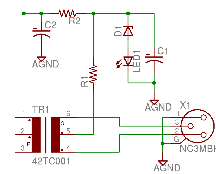
Help with a schematic please
A project is underway to construct the CountryHick DI as illustrated on DIYFactory, incorporating a few minor modifications. The final design aims to be a 1U unit with four inputs.
The CountryHick DI (Direct Injection) box is a crucial tool in...

Designing Multiple Output Power Supplies With Topswitch
This application note describes a digital blood pressure meter concept that utilizes integrated pressure sensor analog signal-conditioning circuitry, microcontroller hardware/software, and a liquid crystal display. The sensing system measures cuff pressure (CP) and extracts pulses for analysis to determine systolic...

Dragon -ZL-2801A DVD machine type switching power supply circuit
The Dragon ZL-2801A is a DVD machine that utilizes a switching power supply circuit. The circuit primarily consists of an AC input circuit, a rectifier filter wave circuit, an oscillation circuit switch, a switch transformer (Tl), a secondary rectifier, and...

voltage Calculating current in a simple circuit
Connect a 12V fan to this circuit that consumes 70mA (0.07A), ensuring the circuit can supply at least that amount of current. There appears to be a misunderstanding regarding the analysis. The voltage drop across the resistor equals the voltage...

Remote tracking circuit schematics
The circuit consists of two main components: (1) a power supply circuit featuring a transformer (T) that steps down AC 220V to 33V, followed by a full-wave rectifier, a filter, and a three-terminal regulator that outputs +24V. This circuit also...

Simple-power-supply
This power supply provides both +9 V and -9 V outputs to replace two 9-V batteries. The rectifier circuit consists of two separate full-wave rectifiers, each connected to the secondary winding of the transformer. The first full-wave rectifier, made up...

-15 V 1-A Regulated Power Supply
The supply receives -20 V from the rectifier/filter which is fed to the collector of the Darlington pnp pass transistor, a TIP105. The base drive to the TIP105 is supplied through resistor R5. The base of the TIP is driven...

how to convert a 9v battery to 3.7v
A regulator circuit is needed for this DIY project. Familiarity with electronic components, circuitry, the use of a multitester, and a soldering iron is essential. The schematic diagram provided can accept an input voltage ranging from 6 to 24 volts...

Power Supply for P.A. Class40
For its maximum result, the final stage of the amplifier should have the proper power supply, as the flowing currents are very high. A Class A amplifier requires attention. These are the rules for the power supply for the Class...