


Negative oxygen ion generator 1
#negative oxygen ion generator
#voltage regulator
#high frequency oscillator
#high voltage generator
#under voltage detection
#steady voltage circuit
#diode
#power supply

Description: This negative oxygen ion generator circuit consists of a steady voltage power supply circuit, an under-voltage detection indication circuit, a high-frequency oscillator, and a high-voltage generator circuit, as illustrated in figure 9-113. The steady voltage power supply circuit is composed of diode VD1, voltage regulator V1, and steady voltage diodes VS1 and VS2, along with an ionization selection switch S, a power supply indication LED VL2, and associated resistor-capacitor components. The under-voltage detection indication circuit includes transistors V3 and V4, steady voltage diode VS3, an under-voltage indication LED VL1, and additional peripheral resistor-capacitor components.
The negative oxygen ion generator circuit is designed to produce negative ions, which can enhance air quality by neutralizing pollutants and allergens. The steady voltage power supply circuit ensures that the system operates reliably by maintaining a consistent voltage level. Diode VD1 rectifies the input voltage, while voltage regulator V1 stabilizes the output voltage, preventing fluctuations that could affect the performance of the circuit. The steady voltage diodes VS1 and VS2 are used to provide additional voltage regulation and protection against voltage spikes.
The ionization selection switch S allows the user to control the ionization process, enabling or disabling the generation of negative ions as needed. The power supply indication LED VL2 serves as a visual indicator, confirming that the circuit is powered and functioning correctly. The peripheral resistor-capacitor components work in conjunction with the aforementioned elements to filter noise and stabilize the circuit operation.
The under-voltage detection circuit plays a critical role in safeguarding the device from operating under insufficient voltage conditions. Transistors V3 and V4 are configured to monitor the voltage levels, and when the voltage drops below a predetermined threshold, steady voltage diode VS3 activates the under-voltage indication LED VL1. This LED serves as a warning signal, alerting the user to the low voltage condition that may compromise the operation of the ion generator.
The high-frequency oscillator and high-voltage generator circuit are essential for generating the necessary high voltage required for ionization. The oscillator produces a high-frequency signal that is then amplified by the high-voltage generator, enabling the circuit to create the electric field necessary for the ionization process. This combination of components ensures that the negative oxygen ions are produced efficiently and effectively, contributing to improved air quality in the surrounding environment.
Overall, this negative oxygen ion generator circuit is a comprehensive design that integrates multiple functional components to achieve its objective of generating negative ions while incorporating safety features to prevent low voltage operation.This negative oxygen ion generator circuit is composed of power supply steady voltage circuit, under voltage detection indication circuit, high frequency oscillator and high voltage generator circuit, it is shown in the figure 9-113. The power supply steady voltage circuit is made of diode VD1, power supply regulator V1, steady voltage diodes VS1,
VS2, ionization selection switch S, power supply indication LED VL2 and peripheral resistor capacitor components. The under voltage detection indication circuit consists of transistors V3, V4, steady voltage diode VS3, under voltage indication LED VL1 and peripheral resistor capacitor components.
The negative oxygen ion generator circuit is designed to produce negative ions, which can enhance air quality by neutralizing pollutants and allergens. The steady voltage power supply circuit ensures that the system operates reliably by maintaining a consistent voltage level. Diode VD1 rectifies the input voltage, while voltage regulator V1 stabilizes the output voltage, preventing fluctuations that could affect the performance of the circuit. The steady voltage diodes VS1 and VS2 are used to provide additional voltage regulation and protection against voltage spikes.
The ionization selection switch S allows the user to control the ionization process, enabling or disabling the generation of negative ions as needed. The power supply indication LED VL2 serves as a visual indicator, confirming that the circuit is powered and functioning correctly. The peripheral resistor-capacitor components work in conjunction with the aforementioned elements to filter noise and stabilize the circuit operation.
The under-voltage detection circuit plays a critical role in safeguarding the device from operating under insufficient voltage conditions. Transistors V3 and V4 are configured to monitor the voltage levels, and when the voltage drops below a predetermined threshold, steady voltage diode VS3 activates the under-voltage indication LED VL1. This LED serves as a warning signal, alerting the user to the low voltage condition that may compromise the operation of the ion generator.
The high-frequency oscillator and high-voltage generator circuit are essential for generating the necessary high voltage required for ionization. The oscillator produces a high-frequency signal that is then amplified by the high-voltage generator, enabling the circuit to create the electric field necessary for the ionization process. This combination of components ensures that the negative oxygen ions are produced efficiently and effectively, contributing to improved air quality in the surrounding environment.
Overall, this negative oxygen ion generator circuit is a comprehensive design that integrates multiple functional components to achieve its objective of generating negative ions while incorporating safety features to prevent low voltage operation.This negative oxygen ion generator circuit is composed of power supply steady voltage circuit, under voltage detection indication circuit, high frequency oscillator and high voltage generator circuit, it is shown in the figure 9-113. The power supply steady voltage circuit is made of diode VD1, power supply regulator V1, steady voltage diodes VS1,
VS2, ionization selection switch S, power supply indication LED VL2 and peripheral resistor capacitor components. The under voltage detection indication circuit consists of transistors V3, V4, steady voltage diode VS3, under voltage indication LED VL1 and peripheral resistor capacitor components.

PM4040F application circuit switching power supply drive
The PM4040F is utilized in switching power supply applications for medium power ranges. It is designed to drive power supplies between 200W and 800W, as illustrated in the accompanying bridge circuit. For power applications below 1000W, an alternative circuit configuration...

12 Volt 30 Amp PSU
Using a single 7812 IC voltage regulator and multiple outboard pass transistors, this power supply can deliver output load currents of up to 30 amps. The input transformer is likely to be the most expensive part of the entire project....

A typical DVD switching power supply circuit
A typical DVD switching power supply circuit is shown in the standby power supply circuit of digital products. It utilizes a switching power supply structure, with the oscillation switch IC EA1623 providing oscillation pulses to the transformer. The secondary output...

AMPLIFIER WITH FORCED EQUILIBRIUM ADAPTOR
Each power supply, whether linear or switching, operates in at least two modes: constant voltage (CV) and constant current (CC). The power supply can function in either mode, with the other serving as a protective mode for both the load...

Increase Regulator Voltage Output Schematic Diagram
It is often necessary to configure a voltage regulator integrated circuit (IC) to provide a higher output voltage than that established by the regulator alone. One method to achieve this is by connecting the common terminal to the midpoint of...

Shortcircuit protected voltage regulator
At this voltage regulator prototype the maximum current, with output shortcircuited it was only 0.5 A, so no overheating occurred. In this DC voltage regulator circuit, T1 is for current limitation. As soon as the voltage on the R2 +...
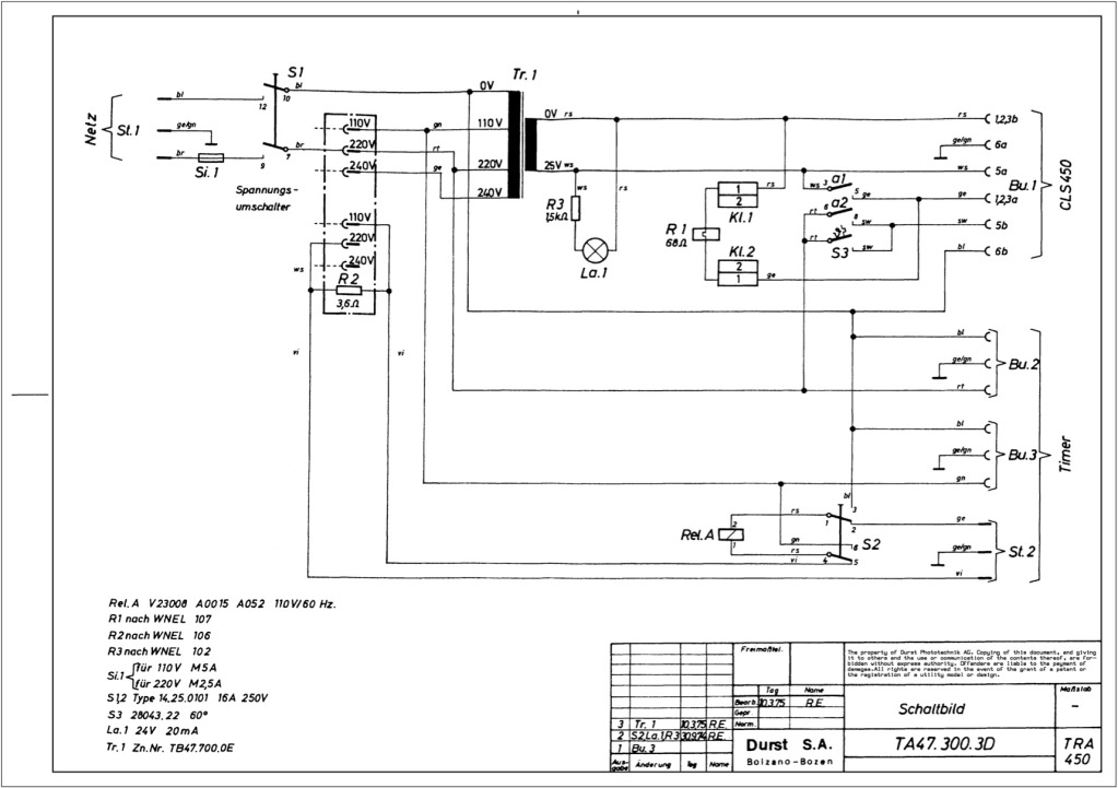
Durst power supplies EST 301 and EST 450
The regulator board of the ES301 has been inspected, revealing that the PCB contacts of the current sensing resistors R42 and R43 are severely burned. There is a nearby group of resistors that also need to be replaced, but their...

regulator
Malcolm Moore's schematic is good, but it is insufficient for someone inexperienced with a soldering iron to create anything functional. Specifically, T1 is a coil of some type, but the configuration, as well as the values for Q1 and Q2,...

Sony KV-S29MHl TV switching power supply (SIR a 80145A) circuit diagram
The circuit of the Sony KV-S29MHl (S Movement series) TV switching power supply (SIR a 80145A) consists of three main sections: (A) the power oscillation part, (B) the regulator part, and (C) the output section.
The Sony KV-S29MHl TV switching power...