


Overvoltage Protection Circuit Circuit
#overvoltage
#protection
#voltage regulator
#shutdown
#circuit testing
#variable voltage
#trip voltage
#safety

Description: When testing a circuit, a variable voltage source with overvoltage shutdown capabilities is highly beneficial. In this circuit, resistor R1 is adjusted to a value 1 to 2 volts below the eventual shutdown threshold. Resistor R2 is responsible for setting the trip voltage. Once this trip voltage is reached, the circuit will shut down the voltage supplied to the circuit under test. To reset the system, R1 should be reduced below the trip threshold, and the reset switch S1 must be pressed.
The described circuit serves as a protective mechanism during the testing of electronic components or circuits. The design incorporates a variable voltage source, which allows for flexibility in testing various devices under different voltage conditions. The inclusion of overvoltage protection is critical, as it safeguards sensitive components from damage due to excessive voltage levels.
Resistor R1 plays a pivotal role in establishing a safe operating range. By adjusting R1 to a value slightly below the shutdown threshold, the circuit ensures that it remains operational until the critical voltage limit is approached. This proactive approach to voltage management allows for accurate testing while preventing accidental overvoltage scenarios.
Resistor R2 is integral to defining the trip voltage, which is the specific voltage level at which the shutdown mechanism activates. The precise calibration of R2 is essential for the reliability of the circuit, as it determines the threshold that triggers the protective shutdown.
When the voltage across R2 reaches the predetermined trip point, the circuit activates a shutdown feature that disconnects the power supply to the circuit under test. This immediate response serves to protect the tested device from potential damage caused by overvoltage conditions.
To restore functionality after a shutdown event, the user must first lower the resistance of R1 to a level below the trip threshold. This adjustment allows the circuit to reset and prepares it for subsequent testing. The activation of the reset switch S1 is a crucial step in this process, as it clears the shutdown state and re-establishes the connection to the voltage source.
Overall, this circuit design emphasizes safety and adaptability in electronic testing environments, making it an invaluable tool for engineers and technicians working with sensitive electronic components. The combination of adjustable resistors and a reset mechanism provides a comprehensive solution for managing voltage levels effectively. When testing a circuit, a source of voltage that is variable and has overvoltage shutdown is veiy useful. In this circuit, Rl is adjusted to 1 to 2 V below the eventual shutdown threshold. R2 sets the trip voltage. When this voltage is reached, the circuit shuts the voltage to the circuit under test down. To reset, reduce Rl belowtrip threshold and depress reset switch SI.
The described circuit serves as a protective mechanism during the testing of electronic components or circuits. The design incorporates a variable voltage source, which allows for flexibility in testing various devices under different voltage conditions. The inclusion of overvoltage protection is critical, as it safeguards sensitive components from damage due to excessive voltage levels.
Resistor R1 plays a pivotal role in establishing a safe operating range. By adjusting R1 to a value slightly below the shutdown threshold, the circuit ensures that it remains operational until the critical voltage limit is approached. This proactive approach to voltage management allows for accurate testing while preventing accidental overvoltage scenarios.
Resistor R2 is integral to defining the trip voltage, which is the specific voltage level at which the shutdown mechanism activates. The precise calibration of R2 is essential for the reliability of the circuit, as it determines the threshold that triggers the protective shutdown.
When the voltage across R2 reaches the predetermined trip point, the circuit activates a shutdown feature that disconnects the power supply to the circuit under test. This immediate response serves to protect the tested device from potential damage caused by overvoltage conditions.
To restore functionality after a shutdown event, the user must first lower the resistance of R1 to a level below the trip threshold. This adjustment allows the circuit to reset and prepares it for subsequent testing. The activation of the reset switch S1 is a crucial step in this process, as it clears the shutdown state and re-establishes the connection to the voltage source.
Overall, this circuit design emphasizes safety and adaptability in electronic testing environments, making it an invaluable tool for engineers and technicians working with sensitive electronic components. The combination of adjustable resistors and a reset mechanism provides a comprehensive solution for managing voltage levels effectively. When testing a circuit, a source of voltage that is variable and has overvoltage shutdown is veiy useful. In this circuit, Rl is adjusted to 1 to 2 V below the eventual shutdown threshold. R2 sets the trip voltage. When this voltage is reached, the circuit shuts the voltage to the circuit under test down. To reset, reduce Rl belowtrip threshold and depress reset switch SI.

Expand integrated three-terminal regulator block circuit output current method
Expand integrated three-terminal regulator block circuit output current method
The integrated three-terminal regulator is a versatile component commonly used in power supply circuits to provide a stable output voltage. This regulator typically consists of three terminals: input, output, and ground. The...

12 Volt 30 Amp PSU
Using a single 7812 IC voltage regulator and multiple outboard pass transistors, this power supply can deliver output load currents of up to 30 amps. The input transformer is likely to be the most expensive part of the entire project....

8V From 5V Regulator Circuit
If locating an 8-V regulator proves difficult, a 5-V unit can serve as a replacement by connecting the regulator as illustrated here.
In electronic circuits, voltage regulators are essential components that maintain a constant output voltage regardless of variations in input...
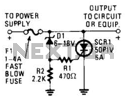
Shutdown Circuit Circuit
Many modern devices have shutdown circuits that are designed to remove power from the device when the voltage rises above a predetermined threshold. This circuit blows a fuse to protect the device under power.
Shutdown circuits are critical components in modern...

Current Limiting Power Supply
This is a 1-amp variable-voltage power supply unit (PSU) that can adjust output voltage from approximately 3V to 24V. It features a maximum output current limit, which is particularly useful when powering up a project for the first time or...

1.3V Power supply
This 1.3V power supply can serve as a replacement for the 1.3V Mercury Cell in any circuit. When a 5V input is applied to the circuit, the voltage drop across the Zener diode D1 will be approximately 2V. The diode...

Variable Dc Power Supply
A Variable DC Power Supply is one of the most useful tools on the electronics hobbyist's workbench. This circuit is not an absolute novelty, but it is simple, reliable, robust, and short-proof, featuring variable voltage up to 24V and variable...
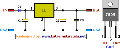
9 Volt 2 Ampere DC Power SupplyCircuit
A simple 9 Volt, 2 amp power supply utilizing a single integrated circuit (IC) regulator. This circuit is straightforward, as the regulator handles the majority of the work. The component used is the 7809 voltage regulator.
The circuit consists primarily of...

High- Or Low-Input Regulator
This regulator provides 12 V at 1 A output with an input voltage range of 8 to 20 V. The output voltage can be adjusted by changing the values of the resistors ll-kii and 2.49 kΩ to achieve 2.21 V...