


PoE+ Circuit Delivers 13W to 70W for Powered Devices (PDs)
#PoE+
#power over ethernet
#MOSFET
#controller
#power management
#30W
#70W
#PDs
#external MOSFET
#power level

Description: A PoE Plus power level of 30 W can be achieved by utilizing an external MOSFET along with a controller that is compatible with the older standard.
Power over Ethernet (PoE) technology enables the delivery of electrical power along with data over standard Ethernet cables, allowing devices such as IP cameras, VoIP phones, and wireless access points to receive power without the need for separate power supplies. The PoE Plus standard, defined by IEEE 802.3at, extends the capabilities of the original PoE standard (IEEE 802.3af) by allowing for a maximum power output of 30 W per port.
To implement a PoE Plus system capable of delivering this power level, an external MOSFET is integrated into the circuit design. The MOSFET serves as a switch that regulates the flow of power to the powered device (PD). The controller, designed for compatibility with the older PoE standard, manages the detection and classification of the powered device, ensuring that the appropriate power level is supplied.
The circuit typically includes a power sourcing equipment (PSE) component that interfaces with the Ethernet cable, supplying power through the spare pairs or the data pairs, depending on the wiring configuration. The external MOSFET is controlled by the PSE, which adjusts the gate voltage to modulate the power delivered to the PD based on its requirements.
In summary, the combination of an external MOSFET and a compatible controller allows the implementation of a PoE Plus system that meets the 30 W power requirement, enabling efficient power delivery for a variety of networked devices while adhering to the established standards.It is possible to implement a PoE Plus-required power level of 30 W, with the aid of an external MOSFET and a controller designed for the older standard..
Power over Ethernet (PoE) technology enables the delivery of electrical power along with data over standard Ethernet cables, allowing devices such as IP cameras, VoIP phones, and wireless access points to receive power without the need for separate power supplies. The PoE Plus standard, defined by IEEE 802.3at, extends the capabilities of the original PoE standard (IEEE 802.3af) by allowing for a maximum power output of 30 W per port.
To implement a PoE Plus system capable of delivering this power level, an external MOSFET is integrated into the circuit design. The MOSFET serves as a switch that regulates the flow of power to the powered device (PD). The controller, designed for compatibility with the older PoE standard, manages the detection and classification of the powered device, ensuring that the appropriate power level is supplied.
The circuit typically includes a power sourcing equipment (PSE) component that interfaces with the Ethernet cable, supplying power through the spare pairs or the data pairs, depending on the wiring configuration. The external MOSFET is controlled by the PSE, which adjusts the gate voltage to modulate the power delivered to the PD based on its requirements.
In summary, the combination of an external MOSFET and a compatible controller allows the implementation of a PoE Plus system that meets the 30 W power requirement, enabling efficient power delivery for a variety of networked devices while adhering to the established standards.It is possible to implement a PoE Plus-required power level of 30 W, with the aid of an external MOSFET and a controller designed for the older standard..

high current mosfet toggle switch
This circuit design is for a high current toggle switch, adapted from the "Toggle Switch Debounced Pushbutton" by John Lundgren. It is intended for applications where the load needs to be switched on from one location and off from another....

Mosfet Buffer Amplifier Circuit
A MOSFET is utilized as a wideband buffer amplifier. T1 is wound on a toroid of approximately specified diameter, using material suitable for the frequency range, typically between 1 MHz and 20 MHz. The turns ratio should be approximately 4:1,...

One-mospower-fet-analog-switch
Utilizing four diodes in an array enables the use of a single MOSPOWER transistor for analog switching. The current flow is managed by maintaining the source-base connection of the MOSFET towards the load. It is essential to select diodes that...

Synchronous controller circuit diagram of a recording transcript
Modern exhibitions utilize extensive sound, light, and electrical technologies for advertising, promotion, and propaganda. This involves various electrical diagrams and control models. Commonly used is an automatic program circuit with pre-recorded commentary, which requires synchronization of two mating times. A...
Power MOSFET Bridge Rectifier
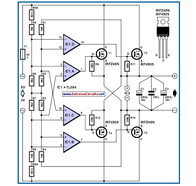
The losses in a bridge rectifier can easily become significant when low voltages are being rectified. The voltage drop across the bridge is approximately 1.5 V.
In a bridge rectifier circuit, the configuration consists of four diodes arranged in a bridge...

Transistor Tutorial MOSFETs
The Metal-Oxide-Semiconductor Field-Effect Transistor (MOSFET) is analogous to the Junction Field-Effect Transistor (JFET) in several aspects. Both types are voltage-driven unipolar devices that rely on either electron or hole movement, but not both, unlike bipolar transistors. A key structural distinction...

switching loads with MOSFETs
The primary concern is that the RDS_on of the utilized MOSFETs, when driven with a 5V gate voltage, is excessively low. Additionally, the reverse voltage that occurs when the MOSFET transitions from the on to the off state can damage...

High power mosfet amplifier circuit ideas
The power amplifier circuit utilizing MOSFET technology has gained significant popularity due to its aggressive sound characteristics when compared to traditional transistors and integrated circuits. It offers both low-frequency and high-frequency responses and is known for its durability. Generally, when...

lamp flasher circuit with mosfet irf511
Capacitors C1 and C2, in conjunction with a speed controller, function by receiving voltage at the gate of the MOSFET. When the voltage on C is applied, it activates the operation of the MOSFET.
In this circuit configuration, capacitors C1 and...