


power supply variable with lm338
#lm338
#voltage regulator
#adjustable power supply
#high current
#lm317
#transistors
#current limit
#DC power
#electronics
#circuit design

Description: This LM338-based power supply can deliver approximately two outputs of 12 to 36 volts at 5 amps each (10 amps in version 2 of this power supply, which includes transistors to increase the current capacity). The design utilizes two LM338 regulators in version 1, though LM317 can also be employed. In version 2, additional transistors will be incorporated to enhance current output. The schematic will feature an adjustable current limit in steps, a current limiter with an LED indicator, and an automatic reset relay to disable the output during short circuits or excessive current draw. Additionally, temperature-sensitive switches will be implemented to shut down the power supply if the cooling plates exceed a specified temperature.
The LM338 voltage regulator is a popular choice for adjustable power supplies due to its ability to provide a stable output voltage. In this design, two LM338 regulators are used in parallel to achieve the desired voltage and current specifications. The output voltage can be adjusted using a pair of resistors configured as a voltage divider, allowing for a range between 12 to 36 volts.
In version 2, the inclusion of additional transistors will significantly enhance the current handling capability of the power supply. These transistors will act as pass elements, allowing the circuit to deliver up to 10 amps by distributing the load more effectively. Proper heat sinking will be essential to manage the thermal performance of these components, ensuring reliable operation under maximum load conditions.
The current limiting feature is implemented using a sense resistor in series with the output. This resistor will allow for the measurement of output current, which can be fed back to a control circuit to adjust the output voltage dynamically, maintaining the current within user-defined limits. The LED indicator will provide a visual cue when the current limit is being reached or has been exceeded.
The automatic reset relay is a critical safety feature that will engage when a short circuit or excessive current is detected. This relay will disconnect the output, preventing damage to the power supply and connected loads. Once the fault condition is resolved, the relay can be reset to restore normal operation.
Temperature-sensitive switches will play an important role in protecting the power supply from overheating. These switches will monitor the temperature of the cooling plates and disconnect the output if the temperature exceeds a predetermined threshold. This feature ensures the longevity of the components and maintains safe operating conditions.
Overall, this LM338-based power supply design offers flexibility, safety, and enhanced performance, making it suitable for various applications requiring adjustable voltage and current outputs.This lm338-v. 1power supply will be able to give something like two times 12- 36 volt and 2x5 amps (10 amps in the v. 2 of this PSU witch includes transistors to get more current from the circuit). I use 2 x lm338 in V. 1 but also lm317 can be used. I will use extra transistors to get the current up i V. 2. Schematic will beequippedwith currentlimitad justablein steps, a current limiter with LED indicator, and i will try to find some way to make areset ablerelay, thanautomaticallydisableoutputwhen short circuit or to high current drawn, Also i have some temperature sensible switches so power supply will shutdown at to high temperature on the cooling plates.
The LM338 voltage regulator is a popular choice for adjustable power supplies due to its ability to provide a stable output voltage. In this design, two LM338 regulators are used in parallel to achieve the desired voltage and current specifications. The output voltage can be adjusted using a pair of resistors configured as a voltage divider, allowing for a range between 12 to 36 volts.
In version 2, the inclusion of additional transistors will significantly enhance the current handling capability of the power supply. These transistors will act as pass elements, allowing the circuit to deliver up to 10 amps by distributing the load more effectively. Proper heat sinking will be essential to manage the thermal performance of these components, ensuring reliable operation under maximum load conditions.
The current limiting feature is implemented using a sense resistor in series with the output. This resistor will allow for the measurement of output current, which can be fed back to a control circuit to adjust the output voltage dynamically, maintaining the current within user-defined limits. The LED indicator will provide a visual cue when the current limit is being reached or has been exceeded.
The automatic reset relay is a critical safety feature that will engage when a short circuit or excessive current is detected. This relay will disconnect the output, preventing damage to the power supply and connected loads. Once the fault condition is resolved, the relay can be reset to restore normal operation.
Temperature-sensitive switches will play an important role in protecting the power supply from overheating. These switches will monitor the temperature of the cooling plates and disconnect the output if the temperature exceeds a predetermined threshold. This feature ensures the longevity of the components and maintains safe operating conditions.
Overall, this LM338-based power supply design offers flexibility, safety, and enhanced performance, making it suitable for various applications requiring adjustable voltage and current outputs.This lm338-v. 1power supply will be able to give something like two times 12- 36 volt and 2x5 amps (10 amps in the v. 2 of this PSU witch includes transistors to get more current from the circuit). I use 2 x lm338 in V. 1 but also lm317 can be used. I will use extra transistors to get the current up i V. 2. Schematic will beequippedwith currentlimitad justablein steps, a current limiter with LED indicator, and i will try to find some way to make areset ablerelay, thanautomaticallydisableoutputwhen short circuit or to high current drawn, Also i have some temperature sensible switches so power supply will shutdown at to high temperature on the cooling plates.

DC panel battery uninterrupted power supply switching circuit
The DC panel battery is commonly utilized in power plants and substations within DC systems. To enhance the safety and reliability of the current system, an uninterrupted power supply switching circuit may be implemented. This circuit includes components such as...

mini drill speed regulator
An integrated voltage regulator connected in reverse to a mini drill allows for speed adjustment within specific limits, maintaining a constant speed regardless of load. The electronic speed control is achieved through a voltage regulator, which can power motors requiring...

5V FET Voltage Regulator
This voltage regulator circuit provides a stable 5V output from unregulated inputs that are greater than 5V. The output voltage stability is satisfactory, with minimal variations.
The voltage regulator circuit utilizes a linear voltage regulator, such as the LM7805, which is...

Lie detector
The circuit diagram of the Lie Detector is illustrated above. It consists of three transistors (TR1 to TR3), a capacitor (C1), two lights or LEDs (L1 & L2), five resistors (R1 to R5), and a variable resistor (VR1). This circuit...

Lamp flasher using LM317
This document describes a lamp flasher circuit utilizing the adjustable voltage regulator IC LM317T. The LM317 can supply a maximum current of 1A, making it suitable for use with lamps up to 12W. This type of circuit has significant applications...

Battery charger using LM317 regulator circuit
This schematic circuit for a battery charger consists of very few components but operates effectively. When power is applied to the circuit, SCR1 remains off, preventing any bias current from flowing to ground. The LM317 voltage regulator is connected to...

Electronics Projects Circuits
Over 1400 top electronics projects and electronic circuits with photos, datasheets, and easy-to-read schematics, along with explanations of how they work and how to build them.
The collection comprises a vast array of electronics projects suitable for enthusiasts and professionals alike....
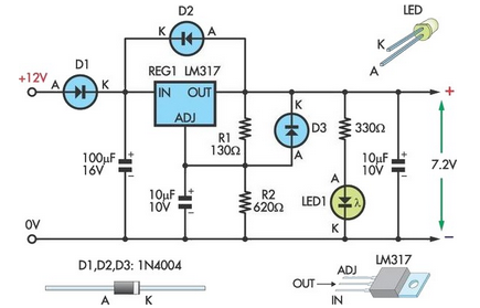
7.2V Battery Replacement Power Supply For Camcorders
This circuit allows an external 12V sealed lead-acid (SLA) battery to power a camcorder that typically operates with an internal 7.2V battery. Obtaining such batteries for older camcorder models can be challenging and costly. The circuit functions as a standard...

1.3V Power supply
This 1.3V power supply can serve as a replacement for the 1.3V Mercury Cell in any circuit. When a 5V input is applied to the circuit, the voltage drop across the Zener diode D1 will be approximately 2V. The diode...