


Programmable power supply design study of the integrated test system of guided missile
#programmable power supply
#voltage regulation
#overvoltage protection
#automatic protection
#DC power supply
#missile test system
#real-time monitoring
#stabilized voltage
#integrated test system
#power management

Description: The programmable power supply is a component of an integrated test system for guided missiles, designed to provide and test various required stabilized direct current voltage supplies for guided missiles. It features real-time monitoring, overvoltage protection, and automatic overload protection. The assembly consists of eight breadboards inserted onto a standard 100 mother strip, including a 40V/-43V power panel, a continuously adjustable 24V power panel, a 20V/22V power panel, a 20V power panel, a 5V/-80V power panel, a power measurement board, and a keyset. The functional block diagram of the programmable power supply is illustrated in Fig. 1. The industrial computer controls the output voltage through a PCL812PG data collection card, utilizing a digital-to-analog converter (D/A) to output the reference voltage that regulates pulse-width modulation (PWM) for continuous output voltage adjustment, while real-time monitoring is achieved through an analog-to-digital (A/D) pathway. The input voltage of 30V is derived from the city power supply of 220V/50Hz, which is converted and filtered through a full-wave rectification circuit and electrolytic capacitors E2 and E3. These capacitors, rated at 2200 µF, are used in parallel to reduce equivalent series resistance (ESR). The design employs a series type switch-mode power supply, with the pulse-width modulator being the SG3524 and the power switching element being the 2N6277. A protective circuit is included to prevent excessive current flow, automatically disconnecting the load under overload conditions. The output circuit consists of a smoothing circuit formed by inductor L1 and electrolytic capacitors E5 and E8, with R5 serving as an artificial load. The selection of output filtering capacitance is critical to minimize output ripple and meet current requirements, calculated as ESRmax = Vout / Iout, where Vout is the ripple range and Iout is one-fourth of the design current requirement. Capacitor E8, a CD28 type with a 5A rating, ensures the ripple remains below the design requirement of 10mV. The programmable power supply, under the control of the industrial computer, adjusts the output voltage based on measured parameters and can perform self-tests and monitoring. Due to the minor phase difference between the 20V and 22V outputs, the same power circuit is utilized, allowing for voltage switching via different reference voltages. The control code P2 from the industrial computer modifies the reference voltage, enabling the output of both 20V and 22V from the same circuit. Control code P0 manages pulse-width modulation for the output. When P2 is high, OC2 remains off, allowing W4 to be adjusted to 1.76k, yielding an output voltage of 22V. Conversely, when P2 is low, OC2 activates, and W3, R23, R21, and R20 are connected in parallel, allowing W3 and R23 to be calculated as 2.4 * R21 R20 = 17.52k, resulting in an output voltage of 20V by adjusting W3 to approximately 3.5k.
The programmable power supply serves as a vital component within the guided missile testing infrastructure, ensuring that various voltage levels are accurately generated and monitored to meet the stringent requirements of missile systems. The integration of advanced control mechanisms, such as PWM and real-time monitoring through an industrial computer, enhances the reliability and functionality of the power supply. The careful selection of components, including high-capacity electrolytic capacitors and robust switching elements, contributes to the overall stability and efficiency of the power supply, enabling it to handle varying loads and conditions while maintaining precise output voltages. This design not only facilitates the testing of missile systems but also ensures that safety mechanisms are in place to protect both the equipment and the operator from potential hazards associated with overvoltage and excessive load conditions.The programmable power supply is the association of one of the integrated test system of guided missile, are used for offering and testing various required direct-flow stabilized voltage supply of guided missile, in addition have functions such as monitoring, overvoltage, excessive load automatic protection, etc. in real time of output voltage. Thi s association is made up of eight pieces of breadboard inserted on the standard 100 mother strip, including 40V/- 43V power panel, 24V continuously adjustable power panel, 20V/ 22V power panel, 20V power panel, 5V/- 80V power panel, power measure and last board, before keyset and behind make up keyset. The functional block diagram of programmable power supply is shown as in Fig. 1, the industrial computer switches over the output voltage of the power through PCL812PG data collecting card figure I/O passway, utilize D/A to output the comparative voltage which regulates PWM in order to control the continuous change of output voltage, monitor the output of the power in real time through A/D passway.
1 The input 30V after voltage transformer of the city power of the incoming circuit 220V/50Hz is exchanged, sends into the switching circuit after full-wave rectification and electrolytic capacitor E2, E3 are filtered. E2, E3 fetch 2200 F, it uses ESR value of reducing the Filtering capacitance in parallel. 2 Adopt the switch stabilized voltage supply of the series type in the circuit design of the switching circuit, the pulse width modulator is SG3524, power switching element is 2N6277, the circuit sets up protective circuit of pressure flow, as the power supply is pressed, at the time of the excessive load, the direct current of the automatic key-out is input, thus the purpose to achieve protective circuit.
The operating frequency of the switching circuit is: 3 The output circuit is made up the smoothing circuit by inductor L1 and electrolytic capacitor E5, E8, R5 is the artificial load. The choice of the Filtering capacitance of the output is very important, output ripple and output current requirement in order to meet minimumly, capacitive ESRmax = Vout / Iout, Vout is a ripple range, Iout is 1/4 of the electric current designing requirement, for this reason, E8 chooses the CD28 type tetrapolar electric capacity, can satisfy 5A Tap, the ripple is smaller than the designing requirement of 10mV.
The programmable power supply, under the control of industrial computer, according to the difference of measurands, switch over and the measurand emerges the required mains voltage, and can make to the programmable power supply up and carry on self test and monitor through the industrial computer. Because 20V/ 22V two kinds of power phase difference are minor, utilize body circuit of the same power, change the output of the power through switching over different reference voltage.
The circuit still changes the comparative reference voltage of the power through the control code P2 of the industrial computer, reach the same circuit and output two pieces of different voltage 20V and 22V Purpose. The control code P0 is used in order to control width modulated pulsingly and export, thus the controlled switch stabilized voltage supply is the work.
When P2 is the high level, OC2 does not turn on, adjusts W4 to 1. 76k, output voltage Vout = =22V; When P2 is the low level, OC2 turns on, W3, R23, R21, R20 connect in parallel, it can have W3 R23 to calculate =2. 4* R21 R20 =17. 52k, it is 20V that can get the output voltage to adjust W3 to about 3. 5k. The programmable power supply is the association of one of the integrated test system of guided missile, are used for offering and testing various required direct-flow stabilized voltage supply of guided missile, in addition have functions such as monitoring, overvoltage, excessive load automatic protection, etc.
in real time of output voltage. This association is made up of eight pieces of breadbo
The programmable power supply serves as a vital component within the guided missile testing infrastructure, ensuring that various voltage levels are accurately generated and monitored to meet the stringent requirements of missile systems. The integration of advanced control mechanisms, such as PWM and real-time monitoring through an industrial computer, enhances the reliability and functionality of the power supply. The careful selection of components, including high-capacity electrolytic capacitors and robust switching elements, contributes to the overall stability and efficiency of the power supply, enabling it to handle varying loads and conditions while maintaining precise output voltages. This design not only facilitates the testing of missile systems but also ensures that safety mechanisms are in place to protect both the equipment and the operator from potential hazards associated with overvoltage and excessive load conditions.The programmable power supply is the association of one of the integrated test system of guided missile, are used for offering and testing various required direct-flow stabilized voltage supply of guided missile, in addition have functions such as monitoring, overvoltage, excessive load automatic protection, etc. in real time of output voltage. Thi s association is made up of eight pieces of breadboard inserted on the standard 100 mother strip, including 40V/- 43V power panel, 24V continuously adjustable power panel, 20V/ 22V power panel, 20V power panel, 5V/- 80V power panel, power measure and last board, before keyset and behind make up keyset. The functional block diagram of programmable power supply is shown as in Fig. 1, the industrial computer switches over the output voltage of the power through PCL812PG data collecting card figure I/O passway, utilize D/A to output the comparative voltage which regulates PWM in order to control the continuous change of output voltage, monitor the output of the power in real time through A/D passway.
1 The input 30V after voltage transformer of the city power of the incoming circuit 220V/50Hz is exchanged, sends into the switching circuit after full-wave rectification and electrolytic capacitor E2, E3 are filtered. E2, E3 fetch 2200 F, it uses ESR value of reducing the Filtering capacitance in parallel. 2 Adopt the switch stabilized voltage supply of the series type in the circuit design of the switching circuit, the pulse width modulator is SG3524, power switching element is 2N6277, the circuit sets up protective circuit of pressure flow, as the power supply is pressed, at the time of the excessive load, the direct current of the automatic key-out is input, thus the purpose to achieve protective circuit.
The operating frequency of the switching circuit is: 3 The output circuit is made up the smoothing circuit by inductor L1 and electrolytic capacitor E5, E8, R5 is the artificial load. The choice of the Filtering capacitance of the output is very important, output ripple and output current requirement in order to meet minimumly, capacitive ESRmax = Vout / Iout, Vout is a ripple range, Iout is 1/4 of the electric current designing requirement, for this reason, E8 chooses the CD28 type tetrapolar electric capacity, can satisfy 5A Tap, the ripple is smaller than the designing requirement of 10mV.
The programmable power supply, under the control of industrial computer, according to the difference of measurands, switch over and the measurand emerges the required mains voltage, and can make to the programmable power supply up and carry on self test and monitor through the industrial computer. Because 20V/ 22V two kinds of power phase difference are minor, utilize body circuit of the same power, change the output of the power through switching over different reference voltage.
The circuit still changes the comparative reference voltage of the power through the control code P2 of the industrial computer, reach the same circuit and output two pieces of different voltage 20V and 22V Purpose. The control code P0 is used in order to control width modulated pulsingly and export, thus the controlled switch stabilized voltage supply is the work.
When P2 is the high level, OC2 does not turn on, adjusts W4 to 1. 76k, output voltage Vout = =22V; When P2 is the low level, OC2 turns on, W3, R23, R21, R20 connect in parallel, it can have W3 R23 to calculate =2. 4* R21 R20 =17. 52k, it is 20V that can get the output voltage to adjust W3 to about 3. 5k. The programmable power supply is the association of one of the integrated test system of guided missile, are used for offering and testing various required direct-flow stabilized voltage supply of guided missile, in addition have functions such as monitoring, overvoltage, excessive load automatic protection, etc.
in real time of output voltage. This association is made up of eight pieces of breadbo

Dual power supply DC power supply circuit
The circuit's output current capacity is influenced by the bulk capacitor Cl. When the capacitance of Cl is changed from 0.7 µF to 2 pF, the output current can be increased from approximately 10 mA to around 20 mA, as...

Overvoltage protection for logic
The Zener diode ZD1 monitors the supply voltage, and if the supply exceeds 6 V, transistor Q1 will activate. This activation causes transistor Q2 to conduct, thereby clamping the voltage rail. The subsequent behavior of the circuit is contingent upon...

capacitor Explaining a car voltage regulator circuit
The circuit regulates approximately 12V from the car battery down to 5V for use by an Atmel AVR microcontroller. The presence of two capacitors on each side of the linear regulator LM7805 raises questions regarding their purpose. It is suggested...
Regulated 12 Volt Supply
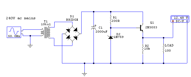
This circuit utilizes a 13-volt zener diode (D2) for voltage regulation. Approximately 0.7 volts are dropped across the base-emitter junction of the transistors, resulting in a higher current output of 12.3 volts. The circuit is capable of supplying loads up...

regulated dc power supply
A low ripple regulated DC power supply designed using transistors is presented. These transistor voltage regulators are suitable for applications requiring high output current. Conventional integrated series regulators, such as the 7805, can only deliver up to 1A. To enhance...

variable voltage and current power supply
An alternative method for utilizing operational amplifiers (op-amps) to regulate a power supply is illustrated below. The power transformer necessitates an additional winding to provide the op-amps with a bipolar voltage of +/- 8 volts. This negative voltage is also...

Fast-overvoltage-protector
This circuit protects expensive portable equipment against all types of improper hookups and environmental hazards that could cause an overvoltage condition. It operates very quickly and does not latch up; rather, it recovers when the overvoltage condition is removed. In...

Simple crowbar
These circuits provide overvoltage protection in the event of a voltage regulator failure or the application of an external voltage. They are designed to be used with a power supply that includes some form of short circuit protection, such as...

CF1 CF2 DC power supply circuit
DC power supply with a shunt, rectifier, filter, limiter, and regulator. The circuit is simple and cost-effective, capable of meeting the requirements. The 6.3V indicator lights HL1 and HL2 indicate the lathe's running and stopping status through a relay control...