


Small current generator circuit
#current generator
#overcurrent relay
#thermal relay
#transformer
#voltage regulation
#electrician tools
#testing equipment
#electrical safety

Description: Electricians sometimes use overcurrent relays, thermal relays, and other devices to perform periodic overcurrent checks with a current generator. A secure running lights transformer, voltage regulator, and meter can be constructed using a small electric current generator. The homemade ship current generator circuit, illustrated in the figure, consists of switches, fuse wire, a regulator, safety running lights transformers, and an ammeter. According to the figure, the line is connected, and the power supply voltage is fed into the regulator. After voltage adjustment, the running lights transformer provides a secondary current voltage that can be adjusted from approximately 0 to 40 mA, allowing for continuous adjustment to meet general overcurrent testing requirements.
The described circuit serves as a practical solution for electricians needing to conduct regular overcurrent checks. At its core, the circuit includes essential components such as switches for controlling the flow of current, fuse wire for protection against overcurrent conditions, and a regulator to maintain a stable output voltage. The safety running lights transformer is integral to stepping down the voltage to a usable level while ensuring the circuit operates safely.
The current generator operates by converting electrical energy into a controlled output that can be manipulated for testing purposes. The voltage regulator plays a crucial role in this setup, allowing for precise adjustments to the output current. This feature is particularly beneficial for testing various electrical devices and systems under different load conditions.
The ammeter included in the circuit provides real-time feedback on the current flowing through the system, enabling electricians to monitor performance and ensure that the current remains within acceptable limits during testing. The adjustable range from 0 to 40 mA is suitable for a variety of applications, making this circuit versatile for different overcurrent testing scenarios.
In summary, the described homemade ship current generator circuit is a valuable tool for electricians, combining essential components to enable effective overcurrent checks. Its design emphasizes safety and functionality, ensuring reliable performance in a range of electrical testing applications.Electrician sometimes overcurrent relays, thermal relays, etc. do periodic overcurrent or check, to use a current generator. Using secure running lights transformer, voltage re gulator and meter can be made by a small electric current generator. FIG homemade ship current generator circuit, which consists of switches, fuse wire, regulator and safety running lights transformers, ammeter, etc., according to the figure the line is connected, the power supply voltage fed zzov regulator after, the transfer pressure, running lights becomes secondary current voltage regulator can be adjusted from about O 40MA, and continuously adjustable, use it to meet the general overcurrent check.
The described circuit serves as a practical solution for electricians needing to conduct regular overcurrent checks. At its core, the circuit includes essential components such as switches for controlling the flow of current, fuse wire for protection against overcurrent conditions, and a regulator to maintain a stable output voltage. The safety running lights transformer is integral to stepping down the voltage to a usable level while ensuring the circuit operates safely.
The current generator operates by converting electrical energy into a controlled output that can be manipulated for testing purposes. The voltage regulator plays a crucial role in this setup, allowing for precise adjustments to the output current. This feature is particularly beneficial for testing various electrical devices and systems under different load conditions.
The ammeter included in the circuit provides real-time feedback on the current flowing through the system, enabling electricians to monitor performance and ensure that the current remains within acceptable limits during testing. The adjustable range from 0 to 40 mA is suitable for a variety of applications, making this circuit versatile for different overcurrent testing scenarios.
In summary, the described homemade ship current generator circuit is a valuable tool for electricians, combining essential components to enable effective overcurrent checks. Its design emphasizes safety and functionality, ensuring reliable performance in a range of electrical testing applications.Electrician sometimes overcurrent relays, thermal relays, etc. do periodic overcurrent or check, to use a current generator. Using secure running lights transformer, voltage re gulator and meter can be made by a small electric current generator. FIG homemade ship current generator circuit, which consists of switches, fuse wire, regulator and safety running lights transformers, ammeter, etc., according to the figure the line is connected, the power supply voltage fed zzov regulator after, the transfer pressure, running lights becomes secondary current voltage regulator can be adjusted from about O 40MA, and continuously adjustable, use it to meet the general overcurrent check.

Variable Voltage Regulation
Controlling the output voltage from a regulator can be made variable in three ways:
1. Using a fixed reference zener diode to increase the output by the value of the zener
2. A variable resistor for variable output, note that...

power supply am farm radio
The ability accumulation is a Tamura 3FD-410 5V bifold primary/dual accessory transformer, available from DigiKey.com at reasonable prices. The transformer's primary windings can be configured in series for 240VAC operation or in parallel for 120VAC operation. This configuration utilizes one...

Classic car battery charging circuit diagram
The circuit operates after a transformer, utilizing a bridge rectifier and conditioning for battery charging. The charging current transformer can be easily adjusted to provide approximately 12V at 100Ah battery charging. The required charging current is 10A, and a 150VA...

psu
The Chameleon II Power Supply Circuits convert the raw input supply into stable voltage outputs necessary for the Chameleon interfaces. The outputs provided are +5V, +12V, and -12V.
The Chameleon II Power Supply Circuits are designed to ensure reliable operation of...
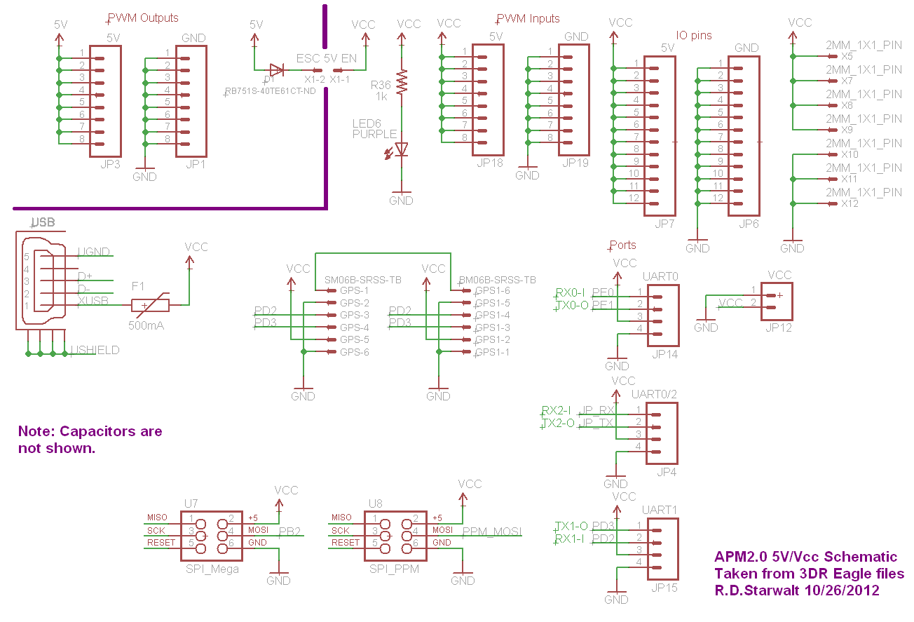
APM2.0 5V/Vcc Schematic
The PWM Output section has been separated into the upper left corner, delineated by a heavy purple line that is bridged by jumper JP1 on the APM2.0. This design choice highlights that diode D1 allows current to pass through JP1,...

How to properly snub transient spikes from a transformer and prevent switch mode power supply burn out
The leads from the transformer to the circuit are quite long (>5m). The 110V side of the transformer has been switched off frequently, which likely caused a spike on the secondary (24V) side. The input pin of the LTC3631 shows...

Build an Experimenters Power Supply
The incoming AC is routed to the primary terminals of a 12.6-volt transformer. The hot side of the AC is connected through a fuse and a single-pole single-throw (SPST) toggle switch. When the switch is in the OFF position, the...

Electrical transformer tutorial
Afroman explains the fundamentals of transformer operation, where to purchase step-down mains transformers, and how to safely wire one to mains voltages. The discussion includes both European and North American wiring standards. The presentation concludes with a brief example of...
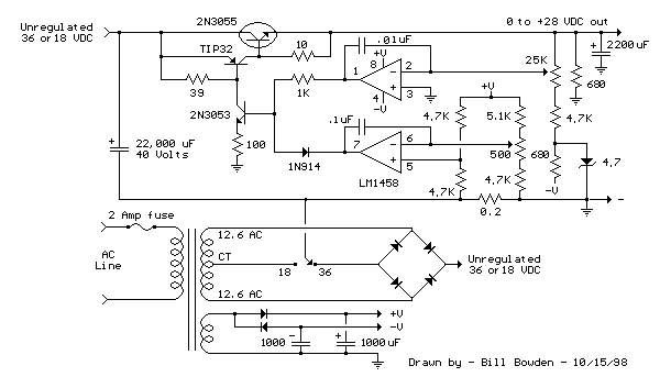
Current and Variable Voltage Power Supply
Another adjustment of application operational amplifiers to adapt a power supply is apparent below. The power supply requires an additional adjustment to supply the op-amps with a bipolar voltage (+/- 8 volts), and the negative voltage is also used to...