


Small Variable Power Supply
#variable power supply
#LM723
#voltage regulation
#current protection
#adjustable output
#over-current protection
#R2
#R3

Description: R2 sets the output voltage. The maximum current is determined by the value of R3: the over-current protection circuitry inside the LM723 senses the voltage across R3 and starts shutting the output stage off as soon as this voltage approaches 0.65 V. This way the current through R3 can never exceed 0.65/R3, even if the output is shorted.
The circuit described involves the use of an LM723 voltage regulator, which is a versatile component commonly used for power supply applications. In this configuration, resistor R2 is critical in determining the output voltage of the regulator. By selecting an appropriate value for R2, the desired output voltage can be achieved as per the voltage divider rule in conjunction with the internal reference voltage of the LM723.
Resistor R3 plays a pivotal role in the current limiting feature of the circuit. The over-current protection mechanism is built into the LM723, which monitors the voltage across R3. When the voltage across R3 approaches 0.65 V, the internal circuitry of the LM723 detects this condition and initiates a shutdown of the output stage. This action prevents excessive current from flowing through the load, thereby protecting both the power supply and the connected components from damage due to overcurrent conditions.
The maximum allowable current through R3 can be calculated using Ohm's Law. Specifically, the current (I) can be expressed as I = 0.65 / R3. This means that, regardless of the load conditions, the current will not exceed this calculated value, ensuring safe operation even in the event of a short circuit at the output.
This design is particularly useful in applications where load conditions may vary significantly, and protection against overcurrent is necessary. The LM723's ability to regulate voltage while simultaneously providing over-current protection enhances the reliability and robustness of the power supply circuit. Proper selection of R2 and R3, along with appropriate heat sinking and component ratings, will ensure optimal performance of the circuit under various operating conditions.R2 sets the output voltage. The maximum current is determined by the value of R3: the over-current protection circuitry inside the LM723 senses the voltage across R3 and starts shutting the output stage off as soon as this voltage approaches 0.65 V. This way the current through R3 can never exceed 0.65/R3, even if the output is shorted.
The circuit described involves the use of an LM723 voltage regulator, which is a versatile component commonly used for power supply applications. In this configuration, resistor R2 is critical in determining the output voltage of the regulator. By selecting an appropriate value for R2, the desired output voltage can be achieved as per the voltage divider rule in conjunction with the internal reference voltage of the LM723.
Resistor R3 plays a pivotal role in the current limiting feature of the circuit. The over-current protection mechanism is built into the LM723, which monitors the voltage across R3. When the voltage across R3 approaches 0.65 V, the internal circuitry of the LM723 detects this condition and initiates a shutdown of the output stage. This action prevents excessive current from flowing through the load, thereby protecting both the power supply and the connected components from damage due to overcurrent conditions.
The maximum allowable current through R3 can be calculated using Ohm's Law. Specifically, the current (I) can be expressed as I = 0.65 / R3. This means that, regardless of the load conditions, the current will not exceed this calculated value, ensuring safe operation even in the event of a short circuit at the output.
This design is particularly useful in applications where load conditions may vary significantly, and protection against overcurrent is necessary. The LM723's ability to regulate voltage while simultaneously providing over-current protection enhances the reliability and robustness of the power supply circuit. Proper selection of R2 and R3, along with appropriate heat sinking and component ratings, will ensure optimal performance of the circuit under various operating conditions.R2 sets the output voltage. The maximum current is determined by the value of R3: the over-current protection circuitry inside the LM723 senses the voltage across R3 and starts shutting the output stage off as soon as this voltage approaches 0.65 V. This way the current through R3 can never exceed 0.65/R3, even if the output is shorted.

LM723 Current Limiting Questions
The LM723 current sense and current limit pins (2 and 3) detect a voltage generated by low-resistance current-limiting resistors. When this voltage reaches a specific threshold, the integrated circuit (IC) either shuts down or restricts the power supply output. The...

Voltage regulator for projection lamp
The circuit regulates the RMS output voltage across a load, specifically a projection lamp, to 100 volts ±2% for input voltages ranging from 105 to 250 volts AC. This regulation is achieved by indirectly sensing the light output of lamp...
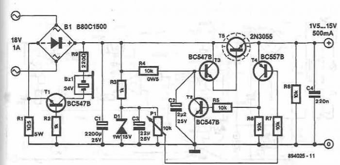
15v variable power supply circuit
This 15V variable power supply electronic project is designed using 2N3055 transistors. The output voltage of this variable power supply can be adjusted in the range between 1.5 and 15 volts. This 2N3055 15V variable power supply can provide a...
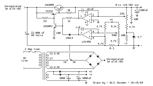
0-28V Variable power supply II
Another method of using opamps to regulate a power supply is shown below. The power transformer requires an additional winding to supply the op-amps with a bipolar voltage (+/- 8 volts), and the negative voltage is also used to generate...
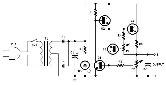
0.7 - 24V /2A Power Supply
A Variable DC Power Supply is one of the most useful tools on the electronics hobbyist's workbench. This circuit is not an absolute novelty, but it is simple, reliable, rugged, and short-proof, featuring variable voltage up to 24V and variable...

how does power supply regulate its
Most power supplies regulate either their output voltage or current at a constant level, depending on the load resistance relative to the power supply's output voltage and current settings. This can be summarized as follows: To accomplish this, most power...

power supply adjustable 0v 30v dc2a
This is a simple regulated power supply circuit based on the well-known LM723 voltage regulator, which drives a transistor Q1 (2N3055). The output voltage regulation is achieved using potentiometer R1, allowing for an adjustable range from 0V to approximately 30V...
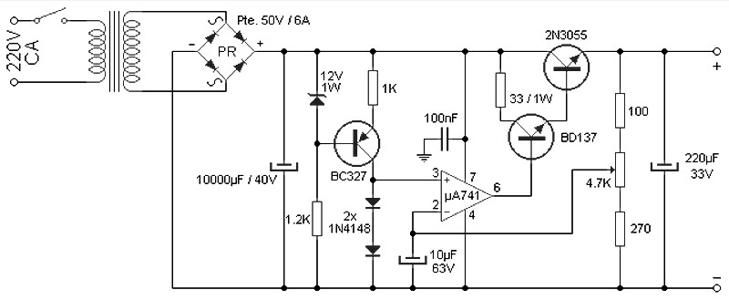
variable 4 a25v power supply
The circuit comprises three stages. The first stage includes a transformer, a bridge rectifier, and a 10,000 µF electrolytic capacitor, which serve to isolate and reduce the voltage while improving and filtering the output. The second stage consists of BC327...

100v / 10ma regulator circuit
The circuit features no-load and short circuit protection mechanisms. To accommodate short circuit conditions, it is necessary to increase resistors R1 and R2 to allow for power dissipation; for example, R1 can be set to 1.2kΩ with a power rating...