


Soldering Iron Control Circuit
#soldering iron
#temperature control
#current control
#TL783
#high-voltage
#integrated regulator
#voltage regulation
#electronics
#DIY

Description: A current control circuit for temperature regulation of a soldering iron utilizes a high-voltage integrated regulator, TL783 (U1). With the specified component values, this circuit is suitable for use with a soldering iron rated at 25 W or less.
The circuit employs the TL783 voltage regulator, which is designed to provide a stable output voltage while allowing for adjustable current control. This feature is essential for maintaining the desired temperature of the soldering iron. The TL783 can handle input voltages up to 125 V and output currents of up to 700 mA, making it a robust choice for this application.
To implement this circuit, several key components are required. The input voltage should be appropriately selected based on the power supply available, ensuring it remains within the operational limits of the TL783. The output voltage can be adjusted using a potentiometer connected to the adjust pin of the regulator, allowing for fine-tuning of the soldering iron's temperature.
Additional components may include capacitors for stability and filtering, as well as resistors to set the desired output voltage. It is critical to choose these components based on the specific characteristics of the soldering iron being used. For a 25 W soldering iron, the output current should be limited to approximately 1 A, which can be achieved by selecting appropriate resistor values in the feedback loop of the TL783.
Thermal management is also a crucial consideration in this circuit design. The TL783 may require a heatsink to dissipate heat generated during operation, especially when operating near its maximum current rating. Proper layout and thermal considerations will enhance the reliability and performance of the soldering iron temperature control circuit.
Overall, this current control circuit provides an effective means of regulating the temperature of a soldering iron, ensuring optimal performance for soldering applications. A current control to temperature regulate a soldering iron uses a high-voltage integrated regulator, TL783 (Ul). With the component values specified, the circuit should be used with a soldering iron of 25 W or less.
The circuit employs the TL783 voltage regulator, which is designed to provide a stable output voltage while allowing for adjustable current control. This feature is essential for maintaining the desired temperature of the soldering iron. The TL783 can handle input voltages up to 125 V and output currents of up to 700 mA, making it a robust choice for this application.
To implement this circuit, several key components are required. The input voltage should be appropriately selected based on the power supply available, ensuring it remains within the operational limits of the TL783. The output voltage can be adjusted using a potentiometer connected to the adjust pin of the regulator, allowing for fine-tuning of the soldering iron's temperature.
Additional components may include capacitors for stability and filtering, as well as resistors to set the desired output voltage. It is critical to choose these components based on the specific characteristics of the soldering iron being used. For a 25 W soldering iron, the output current should be limited to approximately 1 A, which can be achieved by selecting appropriate resistor values in the feedback loop of the TL783.
Thermal management is also a crucial consideration in this circuit design. The TL783 may require a heatsink to dissipate heat generated during operation, especially when operating near its maximum current rating. Proper layout and thermal considerations will enhance the reliability and performance of the soldering iron temperature control circuit.
Overall, this current control circuit provides an effective means of regulating the temperature of a soldering iron, ensuring optimal performance for soldering applications. A current control to temperature regulate a soldering iron uses a high-voltage integrated regulator, TL783 (Ul). With the component values specified, the circuit should be used with a soldering iron of 25 W or less.

High-Voltage Pulse Generator
If you have ever wanted a high-voltage generator to create impressive lightning effects, conduct Kirlian photography experiments, or experiment with neon lights, this project is ideal. It describes a laboratory pulse generator utilizing an auto-ignition coil, capable of delivering a...

Simple Electrification Unit
The circuit is designed for conducting safe experiments with high-voltage pulses and operates similarly to an electrified fence generator. The pulse repetition frequency (PRF) is dictated by the time constant of the R1-C3 network within the feedback loop of operational...

High-Voltage Pulse Supply
This high-voltage pulse supply generates pulses up to 30 kV. Q1 and Q2 form a multivibrator in conjunction with peripheral components R1 through R6, and C1, C2, C3, C5, C6, and D2. R9 adjusts the pulse repetition rate, while R2...
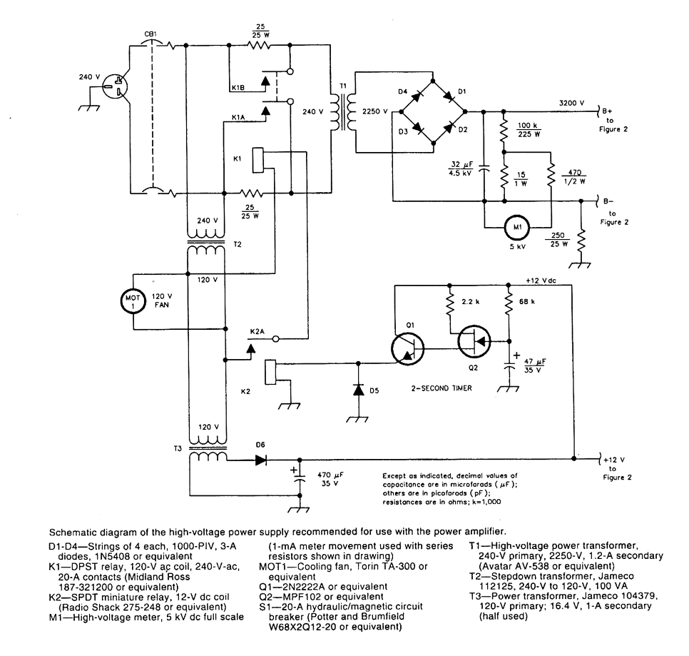
12_kW_144_MHz_AMPLIFIER_POWER_SUPPLY
A schematic diagram of the high-voltage power supply recommended for use with the power transformer. This power supply can also be used for other equipment with similar requirements. CAUTION: hazardous high voltages.
The high-voltage power supply schematic is designed to provide...
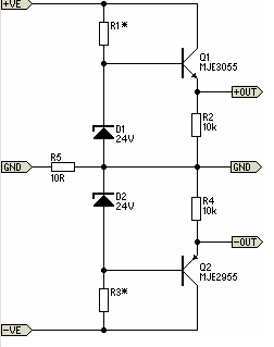
Simple Pre-Regulator
There will be many occasions when it is beneficial to utilize the P05 supply module sourced from a higher voltage supply. For instance, this could be advantageous when integrating balanced inputs.
The P05 supply module is designed to facilitate the conversion...

High-voltage isolation switch operation display circuit
High-voltage isolation switches must not be connected to loads that could create an arc, which may lead to a short circuit between the high-voltage bus and result in accidents that endanger both equipment and personnel safety. Consequently, high-voltage switchgear incorporates...
12_kW_144_MHz_AMPLIFIER_POWER_SUPPLY
A schematic diagram of the high-voltage power supply recommended for use with the power transformer. This power supply can also be used for other equipment with similar requirements. CAUTION: hazardous high voltages.
The high-voltage power supply schematic is designed to provide...

capacitor Explaining a car voltage regulator circuit
The circuit regulates approximately 12V from the car battery down to 5V for use by an Atmel AVR microcontroller. The presence of two capacitors on each side of the linear regulator LM7805 raises questions regarding their purpose. It is suggested...
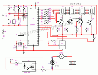
Temperature Control Circuit by Fan
The circuit is designed for temperature control using a fan. It can regulate temperature and also provides temperature indication. All the functions mentioned are monitored.
The temperature control circuit utilizes a fan to maintain a desired ambient temperature within a specified...