


Stabilized Adjustable Power Supply 0-15V/5A
#regulated
#adjustable
#voltage control
#current limit
#heatsink
#transistor
#voltage regulator
#power loss
#0-15V
#5A

Description: This regulated power supply is adjustable between a few volts and 15V using P1, while P2 is used to set the upper limit at 15.0V. The value of R6 is calculated as 0.7V divided by Imax, where Imax represents the maximum current. For Imax set at 5A, R6 will be 0.14 ohms. Components T1 and T2 require heatsinks due to significant power losses that occur at low output voltages and maximum current levels. To mitigate these losses, a lamp can be connected in parallel.
This regulated power supply circuit is designed to provide a stable voltage output that can be finely tuned to meet specific requirements. The adjustment of output voltage is facilitated by potentiometer P1, allowing the user to set the desired voltage anywhere from a minimum value up to a maximum of 15V. The second potentiometer, P2, serves to establish the upper voltage limit, ensuring that the output does not exceed 15.0V during operation.
The resistor R6 plays a crucial role in current regulation, where its value is determined by the formula R6 = 0.7V / Imax. This relationship indicates that as the maximum current (Imax) increases, the resistance value must decrease correspondingly to maintain the voltage drop across R6 at 0.7V. For a maximum current of 5A, R6 is specified to be 0.14 ohms. This low resistance is necessary to allow sufficient current flow while maintaining voltage regulation.
Thermal management is an essential consideration in the design of this power supply, particularly for the transistors T1 and T2. Due to the inherent power losses that occur when the output voltage is low and the current is at its maximum level, these components generate considerable heat. Therefore, the inclusion of heatsinks is critical to dissipate this heat effectively and prevent thermal overload.
To further enhance efficiency and reduce power losses, a lamp can be connected in parallel with the output load. This configuration allows for better energy distribution and can help manage the thermal characteristics of the circuit. The lamp acts as a load that can absorb excess power, thereby reducing the stress on the transistors and improving the overall performance of the power supply.
In summary, this regulated power supply circuit is a versatile solution for providing adjustable voltage levels, with careful attention paid to component selection and thermal management to ensure reliable operation under varying load conditions.This regulated power supply can be adjusted between a few volts and 15V with P1 and with P2 adjust the upper limit ( 15. 0V ). R6 value is 0. 7V / Imax where Imax is the maximum current. At Imax = 5A, R6 is 0. 14 © T1 and T2 must have heatsinks because power losses are great at a low output voltage and a Imax equal current but you can connect the lam
p L to reduce this losses.
This regulated power supply circuit is designed to provide a stable voltage output that can be finely tuned to meet specific requirements. The adjustment of output voltage is facilitated by potentiometer P1, allowing the user to set the desired voltage anywhere from a minimum value up to a maximum of 15V. The second potentiometer, P2, serves to establish the upper voltage limit, ensuring that the output does not exceed 15.0V during operation.
The resistor R6 plays a crucial role in current regulation, where its value is determined by the formula R6 = 0.7V / Imax. This relationship indicates that as the maximum current (Imax) increases, the resistance value must decrease correspondingly to maintain the voltage drop across R6 at 0.7V. For a maximum current of 5A, R6 is specified to be 0.14 ohms. This low resistance is necessary to allow sufficient current flow while maintaining voltage regulation.
Thermal management is an essential consideration in the design of this power supply, particularly for the transistors T1 and T2. Due to the inherent power losses that occur when the output voltage is low and the current is at its maximum level, these components generate considerable heat. Therefore, the inclusion of heatsinks is critical to dissipate this heat effectively and prevent thermal overload.
To further enhance efficiency and reduce power losses, a lamp can be connected in parallel with the output load. This configuration allows for better energy distribution and can help manage the thermal characteristics of the circuit. The lamp acts as a load that can absorb excess power, thereby reducing the stress on the transistors and improving the overall performance of the power supply.
In summary, this regulated power supply circuit is a versatile solution for providing adjustable voltage levels, with careful attention paid to component selection and thermal management to ensure reliable operation under varying load conditions.This regulated power supply can be adjusted between a few volts and 15V with P1 and with P2 adjust the upper limit ( 15. 0V ). R6 value is 0. 7V / Imax where Imax is the maximum current. At Imax = 5A, R6 is 0. 14 © T1 and T2 must have heatsinks because power losses are great at a low output voltage and a Imax equal current but you can connect the lam
p L to reduce this losses.

Hand-held-transceiver-dc-adapter
This adapter provides a regulated 9-V source for operating a Kenwood TR-2500 hand-held transceiver in a vehicle. The mounting tab of the LM317T is electrically connected to its output pin, which should be considered during the construction of the adapter....
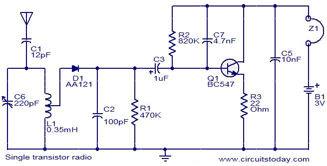
BC547 Single Transistor Radio
The circuit diagram of a simple radio that uses one transistor and a few other passive components. Component: Diode, Capacitor, Inductor, Resistor.
The circuit design for a simple radio receiver typically incorporates a single transistor as the active amplification element, along...

Current Limit Circuit for Voltage Regulator
This is a cost-effective circuit that incorporates precise current limiting functionality into a voltage regulator.
The circuit described is designed to enhance the performance of a voltage regulator by integrating a current limiting feature. This is particularly beneficial in applications where...

The NOT gate
The single-transistor inverter circuit discussed earlier is too simplistic for practical use as a gate. Real inverter circuits utilize multiple transistors to enhance voltage gain, ensuring that the final output transistor is either in full cutoff or full saturation, while...

Transistor regulator circuit can adjustable output voltage
This circuit maintains a constant voltage, with an adjustable output voltage. It serves to reduce the input voltage while keeping the voltage constant. The amplifier model used is the Q1 2N3904 in a common-emitter configuration. This configuration allows the voltage...

Bedini SSG
The transistor activates, causing the magnet to move away. When the transistor deactivates, the energy stored in the coil collapses, directing its flow into the charging battery. As the next magnet approaches, the cycle repeats. This process effectively recaptures energy...

Courtesy light extender
Most car door switches are single-pole switches, with one side grounded. When the door is opened, the switch grounds the other line, completing the light circuit. In vehicles where the negative terminal of the battery is connected to the chassis,...
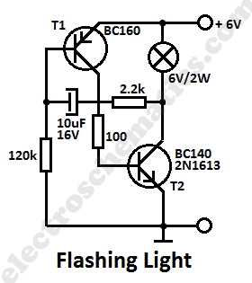
Flashing Light Circuit with Transistors
This simple flashing light circuit operates at 6 volts and 0.5A, exhibiting low current consumption when the light bulb is turned off. The frequency of the flashing is predetermined.
The circuit consists of a power supply, typically a battery or a...

Symmetric Noise Source
When a transistor junction operates in Zener breakdown as a noise source, the resulting noise signal exhibits asymmetry in amplitude. This issue can be addressed by employing two transistors as independent noise sources. One transistor is connected with a series...