


TDA4863AJ Basic Application Circuit a
#TDA4863AJ
#flyback
#voltage regulator
#negative supply
#positive supply
#power management
#circuit design
#electronics

Description: The TDA4863J basic application circuit operates with a positive supply voltage (VP), a flyback power supply voltage (VF), and a negative supply voltage (VN). The input signal is provided from the sawtooth signal input at pins 6 and 7, which connects to the differential input stage. The output is generated from the vertical output stage at pin 5 after amplifying the sawtooth voltage. This output is processed through a vertical complementary push-pull output stage, which drives the sawtooth voltage of the power amplifier. The resulting sawtooth deflection current creates a magnetic field necessary for imaging, controlling the electron beam to scan linearly across the display. During the retrace period, a retrace generator supplies power to the vertical output stage, ensuring minimal power consumption and a short retrace time. The vertical output stage includes temperature limit protection; when the temperature sensor (T1) reaches 150°C, it reduces the output current to protect the chip from overheating and damage. The typical value for capacitor Cs2 is 150nF, optimizing retrace time and noise performance.
The TDA4863J circuit is designed for efficient vertical deflection in display applications, utilizing a combination of voltage supplies to manage the operational requirements. The differential input stage is crucial for processing the sawtooth signal, which is fundamental for generating the vertical deflection required for raster scanning in cathode-ray tube (CRT) displays or similar technologies.
The push-pull output stage enhances the performance of the vertical output by providing sufficient current to drive the deflection coils, which are responsible for directing the electron beam across the screen. The sawtooth waveform produced is tailored to ensure that the beam moves smoothly and accurately, with the retrace generator playing a vital role in minimizing power consumption during the non-active scanning period.
Temperature protection mechanisms are essential for maintaining the reliability of the circuit. The inclusion of a temperature sensor (T1) allows for real-time monitoring of the vertical output stage's thermal conditions. If the temperature exceeds the threshold, the circuit intelligently reduces the output current, preventing potential thermal damage to the TDA4863J chip.
The choice of capacitor Cs2 at 150nF is a critical design parameter, affecting both the retrace time and the noise performance of the circuit. Proper selection of this component ensures that the circuit operates within optimal parameters, delivering high-quality output while minimizing interference. Overall, the TDA4863J circuit exemplifies a well-engineered solution for managing vertical deflection in electronic displays, balancing performance, efficiency, and safety. As shown for the TDA4863J basic application circuit. When the positive supply voltage VP, VF flyback power supply voltage and a negative supply voltage VN to work together with the circuit, the input signal from the sawtooth signal input 6 feet and 7 feet to the inside of the differential input stage of the inverting input terminal and inverting input terminal, the output from the vertical output stage 5 feet after sawtooth voltage amplification. Wherein, subject to the vertical complementary push-pull output stage output amplifier, the sawtooth voltage of the power amplifier, a sawtooth deflection current produces a magnetic field required for imaging through the deflection coils controlling the electron beam scans linearly.
During retrace, retrace generator to supply power to the vertical output stage, so as to have minimal power consumption in a short retrace time. Vertical output stage has a temperature limit protection, when T1 150 starts to decrease when the vertical output stage output current to protect the chip, so that will not overheat and damage.
Cs2 typical value 150nF, then retrace time and the best noise performance.
The TDA4863J circuit is designed for efficient vertical deflection in display applications, utilizing a combination of voltage supplies to manage the operational requirements. The differential input stage is crucial for processing the sawtooth signal, which is fundamental for generating the vertical deflection required for raster scanning in cathode-ray tube (CRT) displays or similar technologies.
The push-pull output stage enhances the performance of the vertical output by providing sufficient current to drive the deflection coils, which are responsible for directing the electron beam across the screen. The sawtooth waveform produced is tailored to ensure that the beam moves smoothly and accurately, with the retrace generator playing a vital role in minimizing power consumption during the non-active scanning period.
Temperature protection mechanisms are essential for maintaining the reliability of the circuit. The inclusion of a temperature sensor (T1) allows for real-time monitoring of the vertical output stage's thermal conditions. If the temperature exceeds the threshold, the circuit intelligently reduces the output current, preventing potential thermal damage to the TDA4863J chip.
The choice of capacitor Cs2 at 150nF is a critical design parameter, affecting both the retrace time and the noise performance of the circuit. Proper selection of this component ensures that the circuit operates within optimal parameters, delivering high-quality output while minimizing interference. Overall, the TDA4863J circuit exemplifies a well-engineered solution for managing vertical deflection in electronic displays, balancing performance, efficiency, and safety. As shown for the TDA4863J basic application circuit. When the positive supply voltage VP, VF flyback power supply voltage and a negative supply voltage VN to work together with the circuit, the input signal from the sawtooth signal input 6 feet and 7 feet to the inside of the differential input stage of the inverting input terminal and inverting input terminal, the output from the vertical output stage 5 feet after sawtooth voltage amplification. Wherein, subject to the vertical complementary push-pull output stage output amplifier, the sawtooth voltage of the power amplifier, a sawtooth deflection current produces a magnetic field required for imaging through the deflection coils controlling the electron beam scans linearly.
During retrace, retrace generator to supply power to the vertical output stage, so as to have minimal power consumption in a short retrace time. Vertical output stage has a temperature limit protection, when T1 150 starts to decrease when the vertical output stage output current to protect the chip, so that will not overheat and damage.
Cs2 typical value 150nF, then retrace time and the best noise performance.

Electronic Projects
This program includes circuit design CAD, simulation, and auto-routing PC layout. PSPICE is also utilized at Unisys, which offers more capabilities but costs six times as much and requires annual renewal. With these requirements and others in mind, a variation...

1.3V Power supply
This 1.3V power supply can serve as a replacement for the 1.3V Mercury Cell in any circuit. When a 5V input is applied to the circuit, the voltage drop across the Zener diode D1 will be approximately 2V. The diode...

Variable 3 - 24 Volt / 3 Amp Power Supply circuit
This regulated power supply can be adjusted from 3 to 25 volts and is current limited to 2 amps as shown, but may be increased to 3 amps or more by selecting a smaller current sense resistor (0.3 ohm). The...

Adjustable output voltage power supply circuit MAX610
The output voltage can be calculated as follows: U = 1.3 (1 + R3 / R4) (V), where R3 and R4 are part of an adjustment potentiometer, allowing for a continuously adjustable output voltage.
The described circuit involves a voltage output...

Temperature compensation of the symmetrical power supply 7812 F007C
The circuit is a temperature-compensated power supply that generates a negative voltage to track positive voltage changes in a symmetrical voltage integrated power supply. It features a three-terminal regulator connected with two identical transistors, leveraging the temperature characteristics of the...

5 A stabilized power supply
This is a simple but powerful nutrition that less than 5 A can deliver. The circuit works by using a normal type 78xx voltage regulator and a buffer transistor. When the output current over 200 mA, then take over the...

12-16V-converter
Many devices operate from a car's 12-V electrical system. Some require 12 V, while others need a lower voltage. An automobile battery's output can vary from 12 to 13.8 V under normal circumstances. The load requirements of the device may...
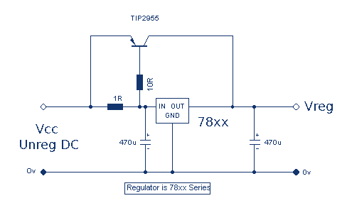
Increasing Regulator Current
Although the 78xx series of voltage regulators are available with different current outputs, you can boost the available current output with this circuit. A power transistor is used to supply extra current to the load, maintaining a constant voltage. Currents...

0-30 VDC Stabilized power supply with current control 0.002-3 A
This is a high quality power supply with a continuously variable stabilised output adjustable at any value between 0 and 30VDC. The circuit also incorporates an electronic output current limiter that effectively controls the output current from a few milliamperes...