


TDA4866 test circuit diagram
#TDA4866
#test circuit
#flyback circuit
#voltage regulator
#supply voltage
#input signal
#circuit diagram
#electronics testing

Description: The TDA4866 test circuit operates with a positive supply voltage (VP) and a feedback voltage (VFB) in conjunction with a flyback circuit. The circuit responds to changes in the input signal, transitioning from one state to another. The input stage features a differential configuration with an inverting input terminal. The output stage generates a vertical sawtooth voltage, which is amplified before being output at specified points. A dummy load resistance simulates a deflection coil, while the output signal is fed back through a reference resistor (Rref). The circuit specifications include VFB at 40V, a maximum of 60V, a feedback resistor (RFB) of 100 ohms, a feedback capacitor (CFB) of 22 microfarads, a capacitor (CSP) ranging from 10 to 330 nanofarads, and a series resistor (RSP) between 10 and 22 ohms.
The TDA4866 test circuit is designed to evaluate the performance of the TDA4866 integrated circuit, which is commonly used in vertical deflection applications in television and display systems. The circuit's operation is initiated by the application of a positive supply voltage (VP), which powers the internal components and facilitates the generation of the necessary waveforms for vertical deflection.
The feedback voltage (VFB) is critical for maintaining the stability and accuracy of the output waveform. In this configuration, the circuit is capable of handling a feedback voltage of 40V, with a maximum allowable voltage of 60V, ensuring that the circuit operates within safe limits under various load conditions. The reference resistor (Rref) plays a pivotal role in determining the feedback loop gain, which influences the overall performance of the circuit.
The differential input stage is designed to receive input signals that represent the desired vertical deflection. The inverting input terminal processes these signals, allowing for the generation of a vertical sawtooth waveform. This waveform is essential for driving the vertical deflection coils in a display system, providing the necessary movement of the electron beam or image pixels.
The output stage amplifies the sawtooth voltage, ensuring that it reaches the appropriate levels required for effective deflection. The use of a dummy load resistance simulates the behavior of a deflection coil, allowing for accurate testing and evaluation of the circuit's performance under realistic conditions.
Capacitors and resistors are selected based on the desired frequency response and stability of the circuit. The feedback capacitor (CFB) of 22 microfarads is chosen to filter out high-frequency noise, while the capacitor (CSP) can vary between 10 and 330 nanofarads, allowing for tuning of the circuit's response. The series resistor (RSP), ranging from 10 to 22 ohms, is used to limit current and protect the circuit from potential overload conditions.
Overall, the TDA4866 test circuit is a comprehensive setup for evaluating the functionality and performance of the TDA4866 integrated circuit in vertical deflection applications, providing essential insights into its operation and characteristics. As shown for the TDA4866 test circuit. When the positive supply voltage VP, supply voltage VFB plus flyback circuit operates when the input signal changes from 1 foot and 2 fee t inside the differential input stage input to the inverting input terminal and inverting input terminal, vertical sawtooth voltage output stage to enlarge after the output of 6 feet and 4 feet. The test circuit used as a dummy load resistance 6 alternative deflection coil, while the output signal is fed back through Rref 9 feet.
40V VFB 60V, RFB 100, CFB 22 F, CSP 10 ~ 330nF, RSP 10 ~ 22 .
The TDA4866 test circuit is designed to evaluate the performance of the TDA4866 integrated circuit, which is commonly used in vertical deflection applications in television and display systems. The circuit's operation is initiated by the application of a positive supply voltage (VP), which powers the internal components and facilitates the generation of the necessary waveforms for vertical deflection.
The feedback voltage (VFB) is critical for maintaining the stability and accuracy of the output waveform. In this configuration, the circuit is capable of handling a feedback voltage of 40V, with a maximum allowable voltage of 60V, ensuring that the circuit operates within safe limits under various load conditions. The reference resistor (Rref) plays a pivotal role in determining the feedback loop gain, which influences the overall performance of the circuit.
The differential input stage is designed to receive input signals that represent the desired vertical deflection. The inverting input terminal processes these signals, allowing for the generation of a vertical sawtooth waveform. This waveform is essential for driving the vertical deflection coils in a display system, providing the necessary movement of the electron beam or image pixels.
The output stage amplifies the sawtooth voltage, ensuring that it reaches the appropriate levels required for effective deflection. The use of a dummy load resistance simulates the behavior of a deflection coil, allowing for accurate testing and evaluation of the circuit's performance under realistic conditions.
Capacitors and resistors are selected based on the desired frequency response and stability of the circuit. The feedback capacitor (CFB) of 22 microfarads is chosen to filter out high-frequency noise, while the capacitor (CSP) can vary between 10 and 330 nanofarads, allowing for tuning of the circuit's response. The series resistor (RSP), ranging from 10 to 22 ohms, is used to limit current and protect the circuit from potential overload conditions.
Overall, the TDA4866 test circuit is a comprehensive setup for evaluating the functionality and performance of the TDA4866 integrated circuit in vertical deflection applications, providing essential insights into its operation and characteristics. As shown for the TDA4866 test circuit. When the positive supply voltage VP, supply voltage VFB plus flyback circuit operates when the input signal changes from 1 foot and 2 fee t inside the differential input stage input to the inverting input terminal and inverting input terminal, vertical sawtooth voltage output stage to enlarge after the output of 6 feet and 4 feet. The test circuit used as a dummy load resistance 6 alternative deflection coil, while the output signal is fed back through Rref 9 feet.
40V VFB 60V, RFB 100, CFB 22 F, CSP 10 ~ 330nF, RSP 10 ~ 22 .

A TREAD sized regulator
The size of the tread was 5 cm by 3 cm. The current design measures 5 cm by 3.3 cm. The regulator's foundation is based on Walt Jung's 1997 article, "Regulator Excels in Noise and Line Rejection," with modifications derived...

Mobile voltage regulator
This simple mobile voltage regulator circuit may save your two-meter or CB transceiver if the voltage regulator fails. The 2N3055 should be heat-sinked if the current drawn by the rig exceeds 2 A during transmission. This circuit will do little...

Dual Regulated Power Supply
The 7815 regulates the positive supply, while the 7915 regulates the negative supply. The transformer should have a primary rating of 240/220 volts for Europe or 120 volts for North America. The center-tapped secondary coil should be rated approximately 18...
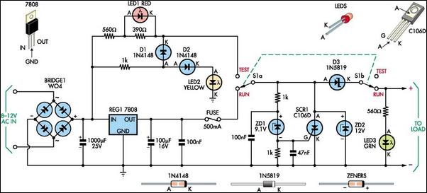
8V DC Power Supply With Over Voltage Protection
This 8V DC power supply is designed for use with high-end electronic equipment. It includes full over-voltage protection to safeguard against regulator failure, whether in the supply itself or in the connected device. The circuit employs a standard full-wave rectifier,...

Multifunction appliance protection circuit diagram
The circuit consists of a DC voltage regulator, a delay circuit, and protection mechanisms for overvoltage and undervoltage. It utilizes the LM7812 integrated voltage regulator to provide a stable 12V output. The protection circuit samples voltage using R2 and potentiometer...

stabilizer circuit
This circuit functions as a high-quality power supply with a continuously variable stabilized output that can be adjusted to any value between 0 and 30 VDC. It includes an electronic output current limiter that effectively regulates the output current from...

0-15 Volt 0-1A Power supply
TR1 provides a constant current to a bank of three zener diodes, thus maintaining a constant voltage independent of supply voltage variations. The resistor Rx is used to sense the PSU output current and to switch off the current to...

Three-terminal voltage regulator integrated fixed a typical wiring circuit
A fixed three-terminal integrated voltage regulator can be directly employed in various electronic devices as a voltage regulator. It features internal protections such as overcurrent protection, thermal protection, and safe operating area protection, making the circuit easy to use, safe,...

Power supply +20V/15A and +12V/3A
The circuit is based on application of National Semiconductor. First is constituted by three voltage regulators LM338 [IC1-2-3] connected in parallel. The each one regulator has the possibility of giving 5 A in his output. Also exists the possibility to...