


Unregulated Power Supply
#unregulated
#full wave rectifier
#transformer
#load current
#power supply design
#rectification
#voltage
#current rating
#electronic circuit

Description: A basic full wave rectified power supply is shown below. The transformer is chosen according to the desired load. For example, if the load requires 12V at 1amp current, then a 12V, 1 amp rated transformer would do. However, when designing power supplies or most electronic circuits, you should always plan for a worst case scenario. With this in mind, for a load current of 1 amp a wise choice would be a transformer with a secondary current rating of 1.5 amp or even 2 amps. Allowing for a load of 50% higher than the needed value is a good rule of thumb.
The described full wave rectified power supply circuit employs a transformer, a rectifier, and filtering components to convert alternating current (AC) to direct current (DC). In this configuration, the transformer steps down the input AC voltage to a desired lower voltage level suitable for the load. For instance, a transformer rated at 12V and 1A is appropriate for a load requiring 12V at 1A. However, to ensure reliability and longevity of the power supply, it is prudent to select a transformer with a higher current rating, ideally 1.5A to 2A, to accommodate potential load variations and prevent overheating.
The rectification process in a full wave rectifier typically utilizes either a bridge rectifier configuration or a center-tapped transformer with two diodes. The bridge rectifier consists of four diodes arranged in a bridge configuration, allowing both halves of the AC waveform to contribute to the output DC voltage. This arrangement is beneficial as it maximizes the efficiency of the rectification process by utilizing the entire input waveform, resulting in a smoother DC output.
After rectification, a filtering stage is often implemented to reduce the ripple voltage present in the output. This is commonly achieved using capacitors, which store charge and release it to smooth out fluctuations in the output voltage. The capacitor value is determined based on the load current and the acceptable ripple voltage; larger capacitance values will yield lower ripple but may increase the physical size and cost of the power supply.
Finally, a voltage regulation stage may be included to maintain a stable output voltage under varying load conditions. This can be achieved through linear voltage regulators or switching regulators, depending on the application requirements, efficiency considerations, and thermal management.
Overall, careful selection of components and consideration for worst-case scenarios are essential in designing a robust full wave rectified power supply that meets the needs of the intended electronic application.A basic full wave rectified power supply is shown below. The transformer is chosen according to the desired load. For example, if the load requires 12V at 1amp current, then a 12V, 1 amp rated transformer would do. However, when designing power supplies or most electronic circuits, you should always plan for a worst case scenario. With this in mind, for a load current of 1 amp a wise choice would be a transformer with a secondary current rating of 1.5 amp or even 2 amps.
Allowing for a load of 50% higher than the needed value is a good rule of thumb.
The described full wave rectified power supply circuit employs a transformer, a rectifier, and filtering components to convert alternating current (AC) to direct current (DC). In this configuration, the transformer steps down the input AC voltage to a desired lower voltage level suitable for the load. For instance, a transformer rated at 12V and 1A is appropriate for a load requiring 12V at 1A. However, to ensure reliability and longevity of the power supply, it is prudent to select a transformer with a higher current rating, ideally 1.5A to 2A, to accommodate potential load variations and prevent overheating.
The rectification process in a full wave rectifier typically utilizes either a bridge rectifier configuration or a center-tapped transformer with two diodes. The bridge rectifier consists of four diodes arranged in a bridge configuration, allowing both halves of the AC waveform to contribute to the output DC voltage. This arrangement is beneficial as it maximizes the efficiency of the rectification process by utilizing the entire input waveform, resulting in a smoother DC output.
After rectification, a filtering stage is often implemented to reduce the ripple voltage present in the output. This is commonly achieved using capacitors, which store charge and release it to smooth out fluctuations in the output voltage. The capacitor value is determined based on the load current and the acceptable ripple voltage; larger capacitance values will yield lower ripple but may increase the physical size and cost of the power supply.
Finally, a voltage regulation stage may be included to maintain a stable output voltage under varying load conditions. This can be achieved through linear voltage regulators or switching regulators, depending on the application requirements, efficiency considerations, and thermal management.
Overall, careful selection of components and consideration for worst-case scenarios are essential in designing a robust full wave rectified power supply that meets the needs of the intended electronic application.A basic full wave rectified power supply is shown below. The transformer is chosen according to the desired load. For example, if the load requires 12V at 1amp current, then a 12V, 1 amp rated transformer would do. However, when designing power supplies or most electronic circuits, you should always plan for a worst case scenario. With this in mind, for a load current of 1 amp a wise choice would be a transformer with a secondary current rating of 1.5 amp or even 2 amps.
Allowing for a load of 50% higher than the needed value is a good rule of thumb.
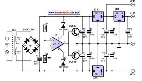
Triple Power Supply
Inexpensive miniature transformers typically offer one or two secondary voltages, which are adequate for producing a set of positive and negative supply voltages.
Miniature transformers are compact devices commonly utilized in various electronic applications, particularly in power supply circuits. These transformers...

Open and Short Circuit Test on Transformer
Open and short circuit tests on a transformer are conducted to determine the equivalent circuit of the transformer, assess its voltage regulation, and evaluate its efficiency.
The open circuit test is performed by applying the rated voltage to the primary winding...

Electric oven circuit
The circuit operates by activating switch SA1, which powers a 220V transformer that converts AC voltage to DC through a bridge rectifier, supplying power to the computer control panel. The temperature for cooking food is set on this control panel,...

Electronic Transformer Coupled Oscillators
The transformer OCL and capacitor C1 create a tank circuit, which is coupled with sufficient turns to drive the grid in the lower left-hand winding. The output circuit is connected through a separate winding. For optimal waveform characteristics in such...

smith kanapadz replication 6
The user intends to purchase a transformer to operate with a 12V battery; however, the transformer in question differs from the one utilized by the user romerouk from Overunity.
The circuit design involves a transformer specifically engineered for low-voltage applications, such...

Simple Power Supply Circuit easy to make Schematic Diagram
Initially, voltage from AC 220V or 110V enters the transformer, which reduces it to 12V AC. This AC voltage is then rectified using either four diodes or a bridge rectifier to convert it to DC voltage. The resulting DC voltage...

transformer Low voltage oscillator for joule thief
A transformer with two input leads and three output leads was used. An LED was connected to two of the output leads, and when a dead AA battery was connected to the input leads, the LED blinked for a brief...

Series DC power supply
A power supply typically consists of a transformer, rectifier, filter, adjustment components, and reference power supply and sampling circuits. Additionally, it may include overload or short circuit protection devices. The circuit begins with a 220V step-down transformer (T) that converts...

voltage Calculating current in a simple circuit
Connect a 12V fan to this circuit that consumes 70mA (0.07A), ensuring the circuit can supply at least that amount of current. There appears to be a misunderstanding regarding the analysis. The voltage drop across the resistor equals the voltage...