


usb pow
#USB
#current limit
#power management
#voltage regulation
#USB hub
#host controller
#500mA
#100mA
#electronic safety

Description: The USB standard limits the current consumption of all USB devices to either 100mA or 500mA, depending on the specifications of the USB hub or host controller (e.g., a computer) supplying the power. Ideally, no USB device should draw more than 500mA from a USB port. However, this is not always the case due to two primary issues. The first issue is high "inrush" current during the startup of certain USB devices. For instance, a USB hard drive attempting to spin up can temporarily draw significantly more than 500mA from its USB port. The second issue arises when high-power USB devices are connected through long USB cables or active USB repeaters, which can lead to substantial voltage drops along the cable length, resulting in some USB devices being underpowered and failing to operate reliably or at all. Additionally, some USB host controllers are known to be "weak" and unable to deliver the full power required by the USB standard. Weak host controllers are commonly found in certain laptops and peripherals with integrated USB hubs, such as computer monitors and printers. USB POW is designed to enable high-powered USB devices to function reliably with underpowered host controllers and hubs. The schematics for USB POW are provided below, with the latest version being revision 1.3. Older schematics are included for historical reference but are not guaranteed to operate correctly. The printed circuit board for USB POW is a standard 2-layer board. Board revision 1.3 allows USB POW to be used with DC power supplies that have a tip = positive and ring = negative polarity, while the previous revision relies on the less common polarity of tip = negative and ring = positive for proper operation.
The USB POW circuit is designed to address the limitations imposed by the USB standard regarding current supply and voltage stability. It incorporates features to manage inrush current, thus preventing excessive current draw during the startup phase of connected devices. This is particularly important for devices such as external hard drives, which may require a surge of current to initiate their operation.
The PCB layout is optimized for minimal resistance and inductance, which helps mitigate voltage drops across long cable runs. The use of quality components, including low-resistance traces and suitable capacitors, ensures that voltage levels remain stable, even under high load conditions. The design also includes protection mechanisms to safeguard both the USB devices and the host controller from potential damage due to overcurrent situations.
USB POW’s compatibility with various DC power supply configurations enhances its versatility, allowing it to be integrated into different systems without the need for extensive modifications. This adaptability makes it suitable for use in a range of applications, from consumer electronics to industrial equipment. The detailed schematics provided for revision 1.3 highlight the circuit's functionality and layout, serving as a guide for implementation and troubleshooting.
In summary, USB POW is a robust solution for ensuring reliable operation of high-power USB devices, particularly in scenarios where host controllers may be inadequate in providing the necessary power. The thoughtful design and engineering principles employed in the USB POW circuit make it an essential component for enhancing USB device performance and reliability in various applications.The USB standard restricts the current consumption of all USB devices to either 100mA or 500mA depending on the specifics of the USB hub and/or host controller (i. e. computer) that is supplying the power. Ideally, no USB device should ever pull more than 500mA of current from a USB port. In reality this is not always the case. There are two main issues that can cause a USB device to attempt to exceed the 100mA or 500mA limit. The first is high "inrush" current during the startup of some USB devices. For example, a USB hard drive trying to spin up can temporarily attempt to pull much more than 500mA from its USB port. The second issue is the connection of high-power USB devices through long USB cables or active USB "repeaters" (really really long USB cables.
) In both cases, the large voltage drop that can occur over the length of such USB cables will cause some USB devices to be under-powered and fail to work reliably. or at all. Lastly, some USB host controllers are notorious for being "weak" and unable to provide the full power required by the USB standard.
Weak host controllers are found in some laptops and peripherals with integrated USB hubs (such as computer monitors, printers, etc. ) USB POW is also ideal for allowing high-powered USB devices to work reliably with under-powered host controllers and hubs.
Below are the schematics for USB POW. The latest schematic is revision 1. 3. Older schematics are also shown, but only for historical information. They are not guaranteed to work correctly. The printed circuit board for USB POW is a standard 2-layer board. Board revision 1. 3 allows USB POW to be used with DC power supplies whose polarity is tip = positive, ring = negative. Board revision relies on the less common polarity tip = negative, ring = positive for proper operation.
Use the following links to:
The USB POW circuit is designed to address the limitations imposed by the USB standard regarding current supply and voltage stability. It incorporates features to manage inrush current, thus preventing excessive current draw during the startup phase of connected devices. This is particularly important for devices such as external hard drives, which may require a surge of current to initiate their operation.
The PCB layout is optimized for minimal resistance and inductance, which helps mitigate voltage drops across long cable runs. The use of quality components, including low-resistance traces and suitable capacitors, ensures that voltage levels remain stable, even under high load conditions. The design also includes protection mechanisms to safeguard both the USB devices and the host controller from potential damage due to overcurrent situations.
USB POW’s compatibility with various DC power supply configurations enhances its versatility, allowing it to be integrated into different systems without the need for extensive modifications. This adaptability makes it suitable for use in a range of applications, from consumer electronics to industrial equipment. The detailed schematics provided for revision 1.3 highlight the circuit's functionality and layout, serving as a guide for implementation and troubleshooting.
In summary, USB POW is a robust solution for ensuring reliable operation of high-power USB devices, particularly in scenarios where host controllers may be inadequate in providing the necessary power. The thoughtful design and engineering principles employed in the USB POW circuit make it an essential component for enhancing USB device performance and reliability in various applications.The USB standard restricts the current consumption of all USB devices to either 100mA or 500mA depending on the specifics of the USB hub and/or host controller (i. e. computer) that is supplying the power. Ideally, no USB device should ever pull more than 500mA of current from a USB port. In reality this is not always the case. There are two main issues that can cause a USB device to attempt to exceed the 100mA or 500mA limit. The first is high "inrush" current during the startup of some USB devices. For example, a USB hard drive trying to spin up can temporarily attempt to pull much more than 500mA from its USB port. The second issue is the connection of high-power USB devices through long USB cables or active USB "repeaters" (really really long USB cables.
) In both cases, the large voltage drop that can occur over the length of such USB cables will cause some USB devices to be under-powered and fail to work reliably. or at all. Lastly, some USB host controllers are notorious for being "weak" and unable to provide the full power required by the USB standard.
Weak host controllers are found in some laptops and peripherals with integrated USB hubs (such as computer monitors, printers, etc. ) USB POW is also ideal for allowing high-powered USB devices to work reliably with under-powered host controllers and hubs.
Below are the schematics for USB POW. The latest schematic is revision 1. 3. Older schematics are also shown, but only for historical information. They are not guaranteed to work correctly. The printed circuit board for USB POW is a standard 2-layer board. Board revision 1. 3 allows USB POW to be used with DC power supplies whose polarity is tip = positive, ring = negative. Board revision relies on the less common polarity tip = negative, ring = positive for proper operation.
Use the following links to:

The Itsy-Bitsy USB Lamp
It connects to the USB port and is ideal for checking motherboard switches and jumper settings. Many users may recall a commercial product from a few years ago, the "Itty Bitty Book Light," which was designed to clip onto a...
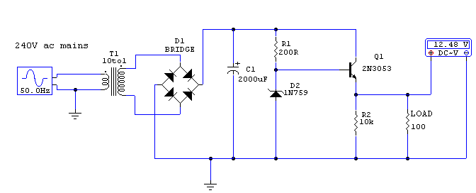
Regulated 12 Volt Supply
This circuit utilizes a 13-volt zener diode (D2) for voltage regulation. Approximately 0.7 volts are dropped across the base-emitter junction of the transistors, resulting in a higher current output of 12.3 volts. The circuit is capable of supplying loads up...

MAX3420 Maxim USB Peripheral Controller
The MAX3420 is a USB peripheral controller chip featuring an SPI bus. This document aims to provide sufficient information for effective utilization of the device in various projects. The MAX3420 simplifies the integration of a USB interface into a circuit...
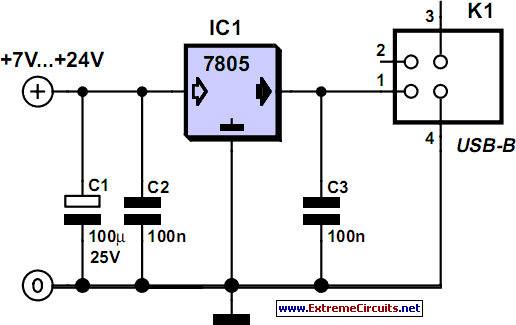
Power Supply For USB Devices
Although a matching charger is typically included in the package, some devices can only be charged via a USB port. This is not surprising for USB MP3 players, which need to dock with a PC for file transfers. However, this...
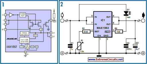
USB Fuse
Life in the 21st century would be nearly unbearable without certain computer peripherals that PC users now consider essential. For instance, the USB-powered teacup warmer is an invaluable productivity tool for users, but it could potentially cause issues if the...

0-30 VDC Stabilized Power Supply with Current Control 0.002-3 A
The circuit begins with a step-down mains transformer featuring a secondary winding rated at 24 V/3 A, which connects across the input points at pins 1 and 2. The quality of the output supply is directly related to the transformer's...

USB LED Lamp Circuit using 5 Volts
A simple USB LED lamp circuit utilizing a 5-volt power supply sourced from a USB port, designed to illuminate a desktop or laptop computer during power outages.
The USB LED lamp circuit operates by converting the 5-volt DC power provided by...

Voltage regulator for projection lamp
The circuit regulates the RMS output voltage across a load, specifically a projection lamp, to 100 volts ±2% for input voltages ranging from 105 to 250 volts AC. This regulation is achieved by indirectly sensing the light output of lamp...

usb
This document outlines a project completed by a team between September 2000 and March 2001 as part of the Engineering Physics degree program at the University of British Columbia. The project involved constructing a USB device utilizing the PIC 16C745...