


Voltage-controlled Current-limited switcher circuit
#voltage-controlled
#current-limited
#switcher
#LM22680
#op-amp
#feedback
#power supply
#current sense
#voltage regulation
#circuit design

Description: The product requires a voltage-controlled, current-limited power supply. Various switcher chips have been used with an op-amp to provide feedback for a current sense voltage to the feedback pin. Currently, an LM22680 is in use, but it has shown inconsistent output voltage results across different boards. The circuit is powered by a standard 24 VDC switching power supply, designed to drive a variable load with a maximum current of 1 amp. Previous circuits have been designed using WebBench. An LM25010 was previously considered, but the 1.25 amp output was excessive. There is a concern about whether it can work with the op-amp feedback circuit, as the datasheet indicates a ripple voltage requirement at the feedback pin that may not be met by the op-amp. All boards are identical, yet some output 21 volts at 1 amp while others only achieve 18 volts under the same 20-ohm load. The unloaded voltage is consistent across boards. Variations in resistance values within the op-amp feedback circuit are suspected, although all components are sourced from the same batch. Significant differences in ripple voltage have also been observed across boards under identical load conditions. Past experiences with National/TI switcher chips have raised concerns about reliability, leading to suggestions from support staff to explore alternative devices. Accurate guidance on suitable devices and configurations is crucial to ensure a consistent and reliable product.
The design of a voltage-controlled, current-limited power supply requires careful consideration of the components involved, particularly when aiming for consistent performance across multiple boards. The LM22680, while a capable chip, has shown variability in output voltage, indicating potential issues with its feedback mechanism or load handling capabilities. The use of an op-amp for feedback is common, but its performance can be influenced by several factors, including the ripple voltage requirements specified in the datasheet.
The LM25010 presents a possible alternative; however, its higher current capacity may not suit all applications, especially in scenarios where precise current limiting is necessary. The interaction between the switcher chip and the op-amp feedback circuit must be thoroughly analyzed to ensure that the ripple voltage falls within acceptable limits. This may involve selecting an op-amp with a higher bandwidth or lower output impedance to better meet the feedback requirements of the LM25010.
To address the observed inconsistencies in output voltage across different boards, a systematic approach to component selection and layout is essential. Ensuring that all components, including resistors in the feedback loop, are matched closely in value can help minimize variations. Additionally, implementing proper PCB design practices, such as minimizing trace lengths and ensuring adequate grounding, can reduce noise and improve stability.
Testing each board under identical conditions will be crucial to identifying any discrepancies in performance. Utilizing precision measurement tools to assess ripple voltage and output stability will provide insight into the root causes of the observed variations. If issues persist, exploring alternative switcher chips from other manufacturers may yield more reliable results, as suggested by previous experiences with National/TI devices.
In summary, achieving a reliable and consistent voltage-controlled, current-limited power supply involves careful selection of components, thorough testing, and adherence to best practices in circuit design and layout. This approach will help mitigate the risks associated with variability and enhance the overall performance of the product.My product requires a voltage-controlled, current-limited power supply and for a number of years I have used various switcher chips with an op-amp to feed back a current sense voltage to the feedback pin. For the last couple of years I have been using an LM22680, but I seem to get variable results board to board.
(Output voltage not consistent) I supply my circuit with an off the shelf 24 VDC switching power supply and the idea is to drive a variable load at a maximum of 1 amp. I have used WebBench for the different circuits that I have used. 3) Is there a better solution I should pursue I have used an LM25010 in the past, but the 1. 25 amps proved to be too much current. Would it work in conjunction with the op-amp feedback circuit (According to the datasheet, their is a ripple voltage requirement at the feedback pin, that may not be provided by the op-amp.
) The boards are exactly the same. The only differences are the components and the solder connections. Some boards will generate 21 volts at 1 amp and others will only generate 18 volts at 1 amp, with the same 20 ohm load. The boards do have the same voltage unloaded. So, I suppose it could be the variation in resistance values of the op-amp feedback circuit, but those components are all from the same run, so it seems unlikely they would vary significantly.
Something I forgot to mention: I have also seen significant variations in ripple voltage present on the output from board to board under the same load conditions. I think it`s safe to say, in general, I have had issues with National/TI switcher chips in the past that were "unofficially" acknowledged by National/TI support staff, who suggested I migrate to other devices.
Being a small company that can`t afford to make a "market mistake" by delivering an unreliable product, I need accurate guidance on what device and configuration will result in a consistent and reliable product. All content and materials on this site are provided "as is". TI and its respective suppliers and providers of content make no representations about the suitability of these materials for any purpose and disclaim all warranties and conditions with regard to these materials, including but not limited to all implied warranties and conditions of merchantability, fitness for a particular purpose, title and non-infringement of any third party intellectual property right.
TI and its respective suppliers and providers of content make no representations about the suitability of these materials for any purpose and disclaim all warranties and conditions with respect to these materials. No license, either express or implied, by estoppel or otherwise, is granted by TI. Use of the information on this site may require a license from a third party, or a license from TI. Content on this site may contain or be subject to specific guidelines or limitations on use. All postings and use of the content on this site are subject to the Terms of Use of the site; third parties using this content agree to abide by any limitations or guidelines and to comply with the Terms of Use of this site.
TI, its suppliers and providers of content reserve the right to make corrections, deletions, modifications, enhancements, improvements and other changes to the content and materials, its products, programs and services at any time or to move or discontinue any content, products, programs, or services without notice.
The design of a voltage-controlled, current-limited power supply requires careful consideration of the components involved, particularly when aiming for consistent performance across multiple boards. The LM22680, while a capable chip, has shown variability in output voltage, indicating potential issues with its feedback mechanism or load handling capabilities. The use of an op-amp for feedback is common, but its performance can be influenced by several factors, including the ripple voltage requirements specified in the datasheet.
The LM25010 presents a possible alternative; however, its higher current capacity may not suit all applications, especially in scenarios where precise current limiting is necessary. The interaction between the switcher chip and the op-amp feedback circuit must be thoroughly analyzed to ensure that the ripple voltage falls within acceptable limits. This may involve selecting an op-amp with a higher bandwidth or lower output impedance to better meet the feedback requirements of the LM25010.
To address the observed inconsistencies in output voltage across different boards, a systematic approach to component selection and layout is essential. Ensuring that all components, including resistors in the feedback loop, are matched closely in value can help minimize variations. Additionally, implementing proper PCB design practices, such as minimizing trace lengths and ensuring adequate grounding, can reduce noise and improve stability.
Testing each board under identical conditions will be crucial to identifying any discrepancies in performance. Utilizing precision measurement tools to assess ripple voltage and output stability will provide insight into the root causes of the observed variations. If issues persist, exploring alternative switcher chips from other manufacturers may yield more reliable results, as suggested by previous experiences with National/TI devices.
In summary, achieving a reliable and consistent voltage-controlled, current-limited power supply involves careful selection of components, thorough testing, and adherence to best practices in circuit design and layout. This approach will help mitigate the risks associated with variability and enhance the overall performance of the product.My product requires a voltage-controlled, current-limited power supply and for a number of years I have used various switcher chips with an op-amp to feed back a current sense voltage to the feedback pin. For the last couple of years I have been using an LM22680, but I seem to get variable results board to board.
(Output voltage not consistent) I supply my circuit with an off the shelf 24 VDC switching power supply and the idea is to drive a variable load at a maximum of 1 amp. I have used WebBench for the different circuits that I have used. 3) Is there a better solution I should pursue I have used an LM25010 in the past, but the 1. 25 amps proved to be too much current. Would it work in conjunction with the op-amp feedback circuit (According to the datasheet, their is a ripple voltage requirement at the feedback pin, that may not be provided by the op-amp.
) The boards are exactly the same. The only differences are the components and the solder connections. Some boards will generate 21 volts at 1 amp and others will only generate 18 volts at 1 amp, with the same 20 ohm load. The boards do have the same voltage unloaded. So, I suppose it could be the variation in resistance values of the op-amp feedback circuit, but those components are all from the same run, so it seems unlikely they would vary significantly.
Something I forgot to mention: I have also seen significant variations in ripple voltage present on the output from board to board under the same load conditions. I think it`s safe to say, in general, I have had issues with National/TI switcher chips in the past that were "unofficially" acknowledged by National/TI support staff, who suggested I migrate to other devices.
Being a small company that can`t afford to make a "market mistake" by delivering an unreliable product, I need accurate guidance on what device and configuration will result in a consistent and reliable product. All content and materials on this site are provided "as is". TI and its respective suppliers and providers of content make no representations about the suitability of these materials for any purpose and disclaim all warranties and conditions with regard to these materials, including but not limited to all implied warranties and conditions of merchantability, fitness for a particular purpose, title and non-infringement of any third party intellectual property right.
TI and its respective suppliers and providers of content make no representations about the suitability of these materials for any purpose and disclaim all warranties and conditions with respect to these materials. No license, either express or implied, by estoppel or otherwise, is granted by TI. Use of the information on this site may require a license from a third party, or a license from TI. Content on this site may contain or be subject to specific guidelines or limitations on use. All postings and use of the content on this site are subject to the Terms of Use of the site; third parties using this content agree to abide by any limitations or guidelines and to comply with the Terms of Use of this site.
TI, its suppliers and providers of content reserve the right to make corrections, deletions, modifications, enhancements, improvements and other changes to the content and materials, its products, programs and services at any time or to move or discontinue any content, products, programs, or services without notice.

Dynamo Frequency Monitor
IC1 is a dual operational amplifier. In this circuit, each op-amp functions as a voltage comparator. When the voltage at the positive input exceeds the voltage at the negative input, the output transitions to a high state. Conversely, when the...

Auto gain control op-amp circuit
An audio signal applied to the input VI is passed through the operational amplifier 741, designated as U2. After amplification, the output signal V2 is sampled and sent to a negative voltage doubler/rectifier circuit composed of diodes CR1 and CR2,...

Alarm Power Supply
This Power Supply is suitable for the Modular Burglar Alarm. However, it has other applications. It is designed to provide an output of 12-volts, with a current of up to 1-amp. In the event of mains failure, the back-up battery...

Audio Triangle Square Wave Generator Using Op-Amp
The circuit illustrates a straightforward triangle and square wave generator utilizing a common dual operational amplifier, the LM1558, capable of producing very low frequencies around 10 kHz. The time interval for one half-cycle is approximately determined by the product of...

100v / 10ma regulator circuit
The circuit features no-load and short circuit protection mechanisms. To accommodate short circuit conditions, it is necessary to increase resistors R1 and R2 to allow for power dissipation; for example, R1 can be set to 1.2kΩ with a power rating...

Sony KV-S29MHl TV switching power supply (SIR a 80145A) circuit diagram
The circuit of the Sony KV-S29MHl (S Movement series) TV switching power supply (SIR a 80145A) consists of three main sections: (A) the power oscillation part, (B) the regulator part, and (C) the output section.
The Sony KV-S29MHl TV switching power...
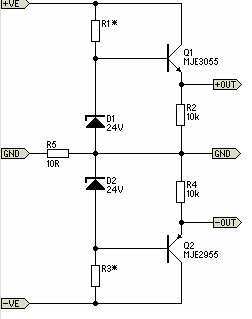
Simple Pre-Regulator
There will be many occasions when it is beneficial to utilize the P05 supply module sourced from a higher voltage supply. For instance, this could be advantageous when integrating balanced inputs.
The P05 supply module is designed to facilitate the conversion...

analog mv switch for digital meters
This circuit utilizes a 4052 as a DC Analog Multiplexer. The inputs to this multiplexer must originate from low-impedance output operational amplifiers (OpAmps). The resistors depicted are unnecessary once the signal conditioning OpAmps are connected. However, 100K resistors can be...

Buffered breakout box
The monitoring circuit consists of four tri-color LEDs driven by an equal number of operational amplifiers configured as inverting amplifiers with a gain of one. Each LED is wired such that it illuminates red when the input to the op...