


1.3W RF Amplifier
#RF amplifier
#2SC1970
#NPN transistor
#signal amplification
#100mW input
#1.3W output
#RF signal
#transistor circuit
#wireless communication
#RF power
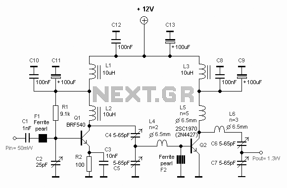
Description: This diagram represents a schematic of an RF amplifier circuit. The circuit is designed to amplify an RF signal from approximately 100 mW input power to 1.3 W output power. It utilizes a general NPN RF transistor, specifically the 2SC1970. Other transistors may also be applied.
The RF amplifier circuit is critical for applications requiring signal enhancement, such as in communication systems. The primary function of this circuit is to increase the power level of the RF signal while preserving its integrity. The 2SC1970 transistor is chosen for its favorable characteristics, including high gain and frequency response, making it suitable for RF applications.
The circuit typically consists of several key components: the NPN transistor, biasing resistors, coupling capacitors, and possibly an output transformer for impedance matching. The biasing resistors ensure that the transistor operates in the active region, allowing for linear amplification. Coupling capacitors are used to block DC components while allowing AC signals to pass, ensuring that the RF signal is amplified without distortion.
The input RF signal is fed into the base of the transistor, where it is amplified by the transistor's gain factor. The amplified output is taken from the collector, where it can be further processed or transmitted. The design may also include feedback mechanisms to stabilize the gain and improve linearity, as well as bypass capacitors to filter out noise.
For optimal performance, careful consideration must be given to the layout of the circuit. Minimizing parasitic capacitance and inductance is essential, particularly at high frequencies, to maintain signal integrity. Additionally, the power supply must be adequately decoupled to prevent fluctuations that could affect the amplifier's performance.
In summary, this RF amplifier circuit schematic provides a robust solution for amplifying RF signals, leveraging the capabilities of the 2SC1970 transistor while allowing for flexibility in component selection to meet specific application requirements.This diagram is a schematic diagram of RF amplifier circuit. The circuit will amplify the RF signal about times, 100mW input power to 1.3W output power. It use a general NPN RF transistor 2SC1970. You may apply other transistors, for exa..
The RF amplifier circuit is critical for applications requiring signal enhancement, such as in communication systems. The primary function of this circuit is to increase the power level of the RF signal while preserving its integrity. The 2SC1970 transistor is chosen for its favorable characteristics, including high gain and frequency response, making it suitable for RF applications.
The circuit typically consists of several key components: the NPN transistor, biasing resistors, coupling capacitors, and possibly an output transformer for impedance matching. The biasing resistors ensure that the transistor operates in the active region, allowing for linear amplification. Coupling capacitors are used to block DC components while allowing AC signals to pass, ensuring that the RF signal is amplified without distortion.
The input RF signal is fed into the base of the transistor, where it is amplified by the transistor's gain factor. The amplified output is taken from the collector, where it can be further processed or transmitted. The design may also include feedback mechanisms to stabilize the gain and improve linearity, as well as bypass capacitors to filter out noise.
For optimal performance, careful consideration must be given to the layout of the circuit. Minimizing parasitic capacitance and inductance is essential, particularly at high frequencies, to maintain signal integrity. Additionally, the power supply must be adequately decoupled to prevent fluctuations that could affect the amplifier's performance.
In summary, this RF amplifier circuit schematic provides a robust solution for amplifying RF signals, leveraging the capabilities of the 2SC1970 transistor while allowing for flexibility in component selection to meet specific application requirements.This diagram is a schematic diagram of RF amplifier circuit. The circuit will amplify the RF signal about times, 100mW input power to 1.3W output power. It use a general NPN RF transistor 2SC1970. You may apply other transistors, for exa..

10.7 MHz RF Amplifier And Filter
The following circuit illustrates a 10.7 MHz RF amplifier and filter circuit diagram. Features include significant capacitances of a power MOSFET.
The 10.7 MHz RF amplifier and filter circuit is designed to amplify radio frequency signals while simultaneously filtering out unwanted...

broadcast band rf amplifier
The circuit features a frequency response from 100 Hz to 3 MHz, with a gain of approximately 30 dB. The field-effect transistor Q1 is configured in a common-source self-biased mode. An optional resistor R1 allows for the adjustment of the...

1W Linear FM Booster
That RF Amplifier is for boosting small fm transmitters and bugs. It uses two Philips 2N4427 and its power is about 1 Watt. At the output, you can drive any linear with BGY133 or BLY87 and so on. Its power...

RF2103P schematic configuration of 915MHz RF amplifier
The circuit illustrated in FIG consists of the RF2103P 915MHz RF amplifier circuit. P1 serves as the outlet, where P1-1 connects to power Vcc, P1-2 connects to ground, and P1-3 is used for the power down control voltage VB. J1...

Remote rf current readout
A suitable pilot lamp is illuminated by a small sample of RF energy and energizes an inexpensive solar cell; the DC current generated by the cell serves as a measure of relative RF power and may be routed to a...

1.3W RF Amplifier Circuit
The following diagram is the circuit diagram of a 20W power amplifier built using the tube component EL34. The EL34 is a well-known tube, ideal for power tube amplifiers. The circuit presented is a complete design that includes both the...

Autodyne Circuit
An Autodyne circuit integrates three functions typically found in separate stages of an RF Receiver into a single circuit. These three stages are the RF amplifier, the Mixer, and the Local Oscillator, which are usually interconnected. In a standard receiver,...

300w rf power amplifier circuit
This is a 300 W RF amplifier designed for FM transmission, capable of operating within the frequency range of 88 to 108 MHz. The amplifier utilizes two TP9383 transistors, enabling it to deliver up to 300 W of output power.
The...

BLY94 100W RF Power Amplifier
A 100W RF power amplifier circuit is constructed using two BLY94 transistors. For additional RF amplifier options, refer to the list below. Components include active components.
The 100W RF power amplifier circuit utilizing BLY94 transistors is designed to amplify radio frequency...