


10GHz White Box Conversion Notes

Description: The objective is to modify the MaCom 10GHz "White Box" unit for ham radio applications. Although the modification instructions are not novel, extensive evaluation of the unit has been conducted, and the performance data provided may be beneficial. Two primary source documents are commonly referenced for the conversion of the White Box. The first is a paper by WA6CGR published in the 1991 Microwave Update, which is accessible online. A PDF copy of this paper is also available. The second document is authored by G3PHO, with a current URL provided. Both papers offer valuable insights as they focus on different extensive modifications of the White Box unit. Users can apply mixer theory to integrate the changes suggested by both authors, resulting in a comprehensive modification, or opt for a simpler approach with minimal alterations. The approach taken by the group involved retuning existing circuits and implementing "high side" local oscillator (LO) injection, which simplifies the process while introducing a reversed sideband and tuning direction. Significant effort has been dedicated to characterizing and optimizing the LO's frequency stability, which operates at 18-20 volts. To facilitate portability, a 12-volt power supply is desired. Both WA6CGR and G3PHO present different methods for achieving this. WA6CGR proposes using an LM317T audio amplifier module as an oscillator at 20kHz, which is then rectified to yield approximately +24 volts, regulated down to 18 volts, while a separate rectifier provides -5 volts for the transmit amplifier bias. In contrast, G3PHO suggests an LM2577-ADJ step-up regulator for generating 18 volts and a separate 5-volt regulator with a 7660 voltage inverter for bias requirements. A circuit diagram of G3PHO's design is provided. Initial construction of the LM317T circuit revealed inefficiency (below 50%) and excessive high-frequency noise, leading to the decision to explore alternative designs. The G3PHO circuit was constructed with satisfactory results, achieving over 90% efficiency, with the LM2577 remaining cool during operation. The current drain from a 13.8V supply is approximately 375mA, while initial startup current is around 700mA but decreases rapidly. The LM-317T circuit drew over 800mA with high idle current. The LM2577 circuit utilizes a high-quality ferrite coil for energy storage, with a 300uH coil chosen based on calculations from the data sheet, specifically the Schott 67127080 coil from Digi-Key. A construction note indicates that only one winding of the coil is used, as paralleling the windings resulted in circuit failure.
The MaCom 10GHz "White Box" unit serves as a versatile platform for ham radio enthusiasts, allowing for modifications that enhance its performance and adaptability. The integration of the WA6CGR and G3PHO modification techniques can lead to a more effective and efficient conversion. The choice of high side LO injection represents a practical compromise, minimizing the need for extensive retuning while still achieving satisfactory operational characteristics.
The power supply design is critical for ensuring stable operation of the modified unit. The LM2577-ADJ step-up regulator presents an effective solution for achieving the necessary voltage levels with high efficiency. By maintaining a low thermal profile, the LM2577 enhances reliability during prolonged use, which is particularly advantageous for portable applications. The careful selection of the ferrite coil also plays a significant role in the performance of the power supply circuit, as it must provide adequate energy storage while minimizing losses.
In summary, the modification of the MaCom 10GHz "White Box" for ham radio use involves a combination of retuning existing circuits and implementing efficient power supply solutions. The insights garnered from the referenced documents contribute to a comprehensive understanding of the necessary modifications, enabling users to achieve optimal performance from their units.To convert the MaCom 10GHz "White Box" (or "Whitebox" for the search engines) unit for ham radio use. Since we`re following in the path of others who`ve already modified these units, there isn`t much new here in the way of modification instructions, but I`ve done a lot of evaluation of the unit and hopefully the performance data presented here will be useful.
There are two source documents that virtually everyone converting the White Box uses. The first is a paper by WA6CGR that was published in the 1991 Microwave Update. It`s available several places on the web, but I have put a copy of Dave`s paper (in PDF format) here. The second conversion document is by G3PHO. The current URL for Peter`s paper is. I also have a. zip file of Peter`s material here. These documents are interesting to compare because each focuses on doing fairly extensive mods to different parts of the White Box unit.
But neither one does much in the areas that the other hacks on. You can apply mixer theory to these papers and do a conversion that`s the sum of the changes both Peter and Dave made (i. e. , lots of work), or the difference (i. e. , not much work at all). Our group took the simple approach and didn`t do any major modifications. We just retuned the existing circuits, and used "high side" LO injection which avoids a major retuning of the local oscillator module at the cost of living with a reversed sideband and tuning direction compared to those who use the more complex LO modification.
I`ve spent most of my time on this project characterizing and optimizing the local oscillator`s frequency stability. See for details of my experiments, and plots of the LO frequency stability. The LO requires 18-20 volts for operation. Since I want to take my 10GHz rig out on the road, I`d like to be able to run the whole system from a 12 volt power supply.
Again, both the WA6CGR and G3PHO papers have different approaches to doing this. `CGR suggests a circuit using an LM317T audio amplifier module as an oscillator running at 20kHz. Dave then rectifies the output to provide about +24 volts, which is regulated down to 18V. A separate rectifier driven from the same signal provides -5 volts for the transmit amplifier bias. G3PHO suggests a circuit using an LM2577-ADJ step-up regulator to generate 18 volts, and a separate 5 volt regulator driving a 7660 voltage inverter to generate the bias requirement. (I`ve attached a circuit diagram of his design here. ) I first built the LM317T circuit, but found that it was very inefficient (well under 50%) and also had a lot of high frequency noise on the output.
I figured that in the end I`d figure out how to filter the noise, but the temperature of the LM317T heatsink convinced me this wasn`t the way to go. Then I built the G3PHO design, and am very happy with it. I`m measuring - hard as it is to believe - greater than 90% efficiency and the LM2577 heatsink remains stone cold after hours of operation.
The current drain from a 13. 8V supply is about 375ma (when the crystal heater is at operating temperature - the starting current is about 700ma but drops pretty rapidly). By contrast, my LM-317T drew over 800ma and the idle current is quite high. The LM2577 circuit uses one somewhat expensive component, a high-quality ferrite coil that provides energy storage.
Peter`s design used a 100uH coil, but my back-of-the-envelope calculation from the data sheet showed that a 300uH coil was more in line. I used a Schott 67127080 (available from Digi-Key) which cost about $13. 00. By the way, here`s a construction hint: The Schott coil has two windings, but this circuit uses only one of them.
I initially paralleled the windings in the hope of reducing series resistance. The power supply didn`t work. When I separated the windings, it took right off. My best guess is that the windings
The MaCom 10GHz "White Box" unit serves as a versatile platform for ham radio enthusiasts, allowing for modifications that enhance its performance and adaptability. The integration of the WA6CGR and G3PHO modification techniques can lead to a more effective and efficient conversion. The choice of high side LO injection represents a practical compromise, minimizing the need for extensive retuning while still achieving satisfactory operational characteristics.
The power supply design is critical for ensuring stable operation of the modified unit. The LM2577-ADJ step-up regulator presents an effective solution for achieving the necessary voltage levels with high efficiency. By maintaining a low thermal profile, the LM2577 enhances reliability during prolonged use, which is particularly advantageous for portable applications. The careful selection of the ferrite coil also plays a significant role in the performance of the power supply circuit, as it must provide adequate energy storage while minimizing losses.
In summary, the modification of the MaCom 10GHz "White Box" for ham radio use involves a combination of retuning existing circuits and implementing efficient power supply solutions. The insights garnered from the referenced documents contribute to a comprehensive understanding of the necessary modifications, enabling users to achieve optimal performance from their units.To convert the MaCom 10GHz "White Box" (or "Whitebox" for the search engines) unit for ham radio use. Since we`re following in the path of others who`ve already modified these units, there isn`t much new here in the way of modification instructions, but I`ve done a lot of evaluation of the unit and hopefully the performance data presented here will be useful.
There are two source documents that virtually everyone converting the White Box uses. The first is a paper by WA6CGR that was published in the 1991 Microwave Update. It`s available several places on the web, but I have put a copy of Dave`s paper (in PDF format) here. The second conversion document is by G3PHO. The current URL for Peter`s paper is. I also have a. zip file of Peter`s material here. These documents are interesting to compare because each focuses on doing fairly extensive mods to different parts of the White Box unit.
But neither one does much in the areas that the other hacks on. You can apply mixer theory to these papers and do a conversion that`s the sum of the changes both Peter and Dave made (i. e. , lots of work), or the difference (i. e. , not much work at all). Our group took the simple approach and didn`t do any major modifications. We just retuned the existing circuits, and used "high side" LO injection which avoids a major retuning of the local oscillator module at the cost of living with a reversed sideband and tuning direction compared to those who use the more complex LO modification.
I`ve spent most of my time on this project characterizing and optimizing the local oscillator`s frequency stability. See for details of my experiments, and plots of the LO frequency stability. The LO requires 18-20 volts for operation. Since I want to take my 10GHz rig out on the road, I`d like to be able to run the whole system from a 12 volt power supply.
Again, both the WA6CGR and G3PHO papers have different approaches to doing this. `CGR suggests a circuit using an LM317T audio amplifier module as an oscillator running at 20kHz. Dave then rectifies the output to provide about +24 volts, which is regulated down to 18V. A separate rectifier driven from the same signal provides -5 volts for the transmit amplifier bias. G3PHO suggests a circuit using an LM2577-ADJ step-up regulator to generate 18 volts, and a separate 5 volt regulator driving a 7660 voltage inverter to generate the bias requirement. (I`ve attached a circuit diagram of his design here. ) I first built the LM317T circuit, but found that it was very inefficient (well under 50%) and also had a lot of high frequency noise on the output.
I figured that in the end I`d figure out how to filter the noise, but the temperature of the LM317T heatsink convinced me this wasn`t the way to go. Then I built the G3PHO design, and am very happy with it. I`m measuring - hard as it is to believe - greater than 90% efficiency and the LM2577 heatsink remains stone cold after hours of operation.
The current drain from a 13. 8V supply is about 375ma (when the crystal heater is at operating temperature - the starting current is about 700ma but drops pretty rapidly). By contrast, my LM-317T drew over 800ma and the idle current is quite high. The LM2577 circuit uses one somewhat expensive component, a high-quality ferrite coil that provides energy storage.
Peter`s design used a 100uH coil, but my back-of-the-envelope calculation from the data sheet showed that a 300uH coil was more in line. I used a Schott 67127080 (available from Digi-Key) which cost about $13. 00. By the way, here`s a construction hint: The Schott coil has two windings, but this circuit uses only one of them.
I initially paralleled the windings in the hope of reducing series resistance. The power supply didn`t work. When I separated the windings, it took right off. My best guess is that the windings

rf remote control encoder and decoder
This document explains two RF 433kHz remote control chips specifically designed for remote control applications. The IC TWS-434, along with its encoder chip HT-12E from Holtek, forms a high-quality transmitter circuit, while the chip RWS-434, paired with the decoder IC...

RF Bug detector
This circuit is not open for discussion. Although working perfectly, it was experimental. I will answer no emails in regards to this circuit. If you are looking for a more serious and reliable bug detector, go to the Countersurveillance Monitor...

Remote ControlCircuit Through RF Without Microcontroller
This circuit illustrates a remote control circuit diagram using RF technology without the use of a microcontroller. Features include a simple remote control circuit that operates via radio frequency.
The remote control circuit operates by transmitting signals through radio waves, enabling...

RF Combo
The RF Combo (A3016) integrates three circuits designed to support the development of circuit boards for Stage Four of a subcutaneous transmitter. The printed circuit board maintains the same outline as the RF Tester (A3014). The SAW Oscillator (A3016SO) replaces...

RF wireless allarm magnetic switch PIC16F84
This circuit was formed to create a wireless alarm from a normal magnetic contact. By fixing the magnet to the leaf of a door, or swing of a drawer, it is easy to reveal the opening. To transmit the signal...

RF-powered sidetone oscillator
A sidetone oscillator is a specific type of audio astable multivibrator. Keying is achieved by turning the oscillator on and off through the application of a positive DC potential, which is generated from the RF signal to the reset terminal...

Simple-ham-band-receiver
This circuit is designed for operation in the 80m band. It utilizes a 365-pF variable capacitor, specifically intended for the broadcast band, which should be equipped with a vernier drive featuring a six-to-one tuning ratio. This configuration enhances the tuning...

TRF1115 RF Down-Converter
The TRF1400 VHF/UHF RZ ASK remote control receiver is specifically designed for RZ ASK (return-to-zero amplitude-shift keyed) communications systems operating in the 200-MHz to 450-MHz band. This device is targeted for use in automotive and home security systems, garage door...
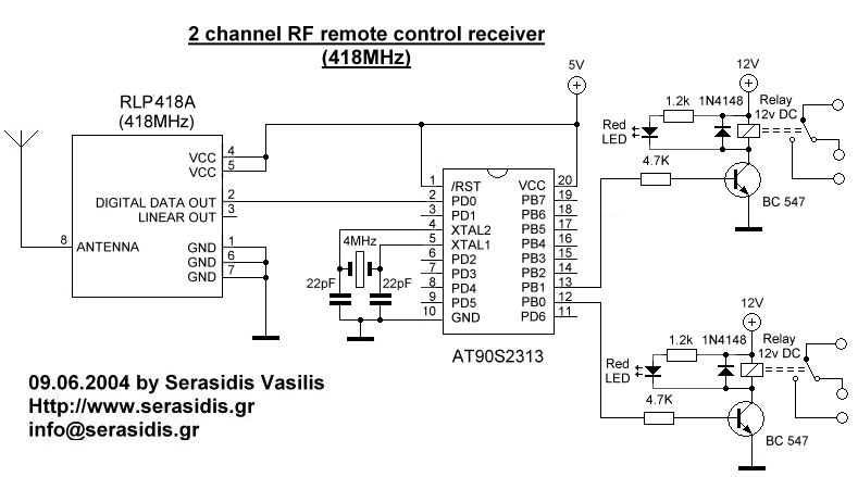
2 channel RF remote control
The basic small-range remote controls are Infrared and RF (Radio Frequency). One of the weaknesses of Infrared is that the signal cannot pass through walls. Therefore, to control a garage door, an RF remote control is necessary. The circuit (transmitter...