


10M Dsb Transmitter Circuit
#DSB transmitter
#10-meter band
#28.322 MHz
#CW operation
#1-W output
#crystal oscillator
#RF circuits
#transmitter circuit

Description: A DSB transmitter is significantly less expensive to construct compared to an SSB transmitter since it does not require filters or phasing networks. This circuit can generate an output of up to 1 watt on the 10-meter band. The frequency of 28.322 MHz, which is a commonly available clock frequency crystal, is utilized. Additionally, continuous wave (CW) operation is supported. A doubly balanced mixer assembly serves as both the modulator and the CW keyer.
The DSB (Double Sideband) transmitter circuit is designed to be cost-effective while providing essential functionality for amateur radio applications. The absence of complex filters and phasing networks simplifies the design and reduces the overall component count, making it attractive for hobbyists and those looking to build transmitters with limited resources.
The circuit operates at a frequency of 28.322 MHz, which aligns with the 10-meter amateur radio band, allowing for effective communication within this frequency range. The use of a commonly available clock frequency crystal ensures that the transmitter can be built with readily accessible components, further enhancing its practicality.
The modulator component of the circuit is implemented using a doubly balanced mixer assembly. This configuration effectively combines the audio frequency signal with the carrier frequency, producing the double sideband output signal. The doubly balanced mixer is known for its high linearity and low distortion, which are crucial for maintaining signal integrity during transmission.
In addition to DSB operation, the circuit incorporates a continuous wave (CW) keyer function. This feature allows for the transmission of Morse code signals, which is an essential mode of communication for many amateur radio operators. The CW keyer can be easily integrated into the existing circuit, providing versatility for users who wish to operate in different modes.
Overall, this DSB transmitter circuit represents a practical solution for those interested in amateur radio, offering a balance between simplicity, cost, and functionality. Its design promotes ease of assembly and operation, making it suitable for both beginners and experienced operators alike. A DSB transmitter is much cheaper to build than an SSB transmitter because no filter or phasing networks are required. This circuit produces up to 1-W output on the 10-meter band. The frequency 28.322 MHz is used, which is a commonly available clock frequency crystal. CW operation is also provided. A doubly balanced mixer assembly is used as a modulator and CW keyer.
The DSB (Double Sideband) transmitter circuit is designed to be cost-effective while providing essential functionality for amateur radio applications. The absence of complex filters and phasing networks simplifies the design and reduces the overall component count, making it attractive for hobbyists and those looking to build transmitters with limited resources.
The circuit operates at a frequency of 28.322 MHz, which aligns with the 10-meter amateur radio band, allowing for effective communication within this frequency range. The use of a commonly available clock frequency crystal ensures that the transmitter can be built with readily accessible components, further enhancing its practicality.
The modulator component of the circuit is implemented using a doubly balanced mixer assembly. This configuration effectively combines the audio frequency signal with the carrier frequency, producing the double sideband output signal. The doubly balanced mixer is known for its high linearity and low distortion, which are crucial for maintaining signal integrity during transmission.
In addition to DSB operation, the circuit incorporates a continuous wave (CW) keyer function. This feature allows for the transmission of Morse code signals, which is an essential mode of communication for many amateur radio operators. The CW keyer can be easily integrated into the existing circuit, providing versatility for users who wish to operate in different modes.
Overall, this DSB transmitter circuit represents a practical solution for those interested in amateur radio, offering a balance between simplicity, cost, and functionality. Its design promotes ease of assembly and operation, making it suitable for both beginners and experienced operators alike. A DSB transmitter is much cheaper to build than an SSB transmitter because no filter or phasing networks are required. This circuit produces up to 1-W output on the 10-meter band. The frequency 28.322 MHz is used, which is a commonly available clock frequency crystal. CW operation is also provided. A doubly balanced mixer assembly is used as a modulator and CW keyer.

UNIVERSAL TEST OSCILLATOR
The crystal is positioned in the feedback path of a Pierce oscillator, situated between the base and collector of transistor Q1, with a 2.5 mH RF choke replacing the tuned collector circuit. The oscillator operates within a frequency range of...

oscillator circuits
This generally results in a square wave if the frequency of oscillation is low enough relative to the amplifier's bandwidth. The schematic of a crystal-controlled oscillator features a low-frequency sine wave oscillator characterized by low distortion, wideband operation, and crystal...

Integrated-am-receiver
A crystal oscillator is used so that a narrow-band hybrid IF filter can be utilized. This circuit includes aerial and local oscillator circuits for a 27-MHz receiver, intended for the remote control of garage doors, projectors, curtains, and similar applications.
The...

Crystal oscillator
International Crystal OF-1 LO oscillator circuit for fundamental-mode crystals that you can find.
The International Crystal OF-1 local oscillator (LO) circuit is designed to operate with fundamental-mode crystals, which are widely used in various frequency generation applications. This oscillator circuit typically...
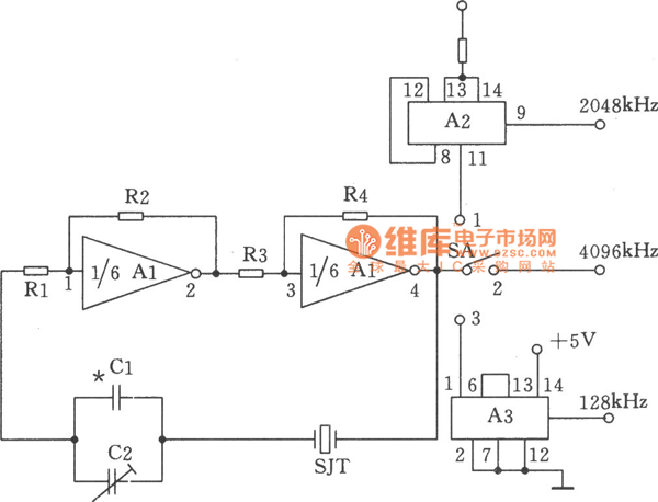
Mutiple Output Crystal Oscillator Sensor
The figure illustrates a multiple output crystal oscillator, which primarily consists of three gates of Al, four resistors, two capacitors, and a crystal. Resistors R1 to R4 offset two inverters within the linear range and are connected between pin 4...

VERY LOW POWER GATED CRYSTAL OSCILLATOR
The circuit controls the output of a continuously operating 32KHz crystal oscillator, directing it to the input of a C-MOS buffer when clock pulses are required. This technique addresses the issue of a slow-starting crystal oscillator by maintaining the oscillator's...
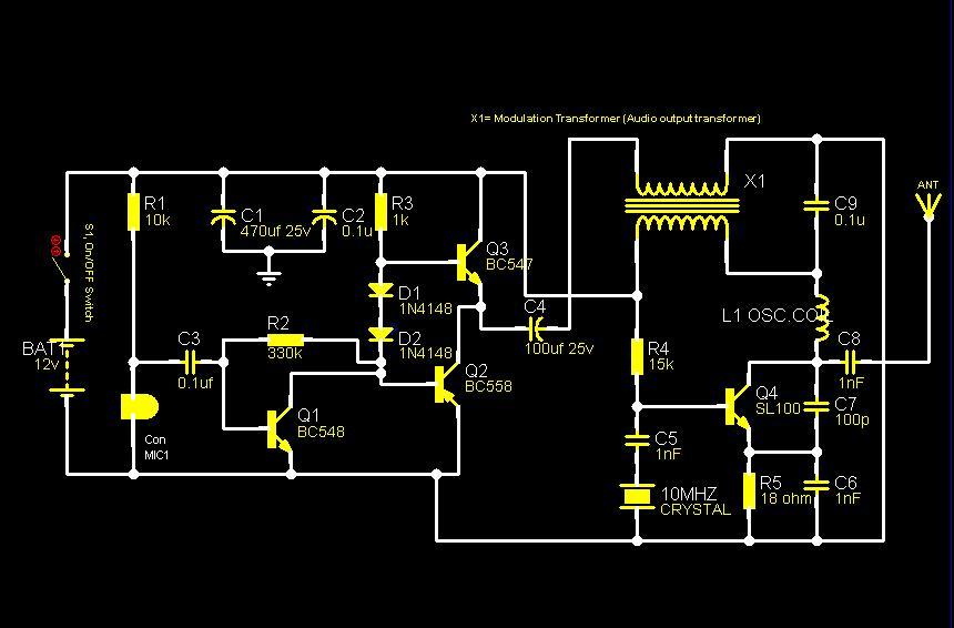
150mW Crystal AM Transmitter PCB
The core component of this circuit is a crystal oscillator utilizing a 10MHz crystal to generate a highly stable carrier frequency. The sound signal from a condenser microphone is amplified by an amplifier circuit comprised of transistors Q1, Q2, and...

Crystal oscillator provides low noise
The oscillator provides an output with high spectral purity while maintaining the typical stability associated with crystal oscillators. The crystal not only sets the oscillator's frequency but also functions as a low-pass filter to eliminate unwanted harmonics and as a...

Crystal Oscillators
The schematic illustrates the division of a crystal oscillator signal by the crystal frequency to achieve a precise 1-second time base with an accuracy of 0.01%. Two cascaded 12-stage counters (CD4040) create a 24-stage binary counter, with specific bits gated...