


144mhz 2m converter
#144MHz
#2 metre signals
#VHF
#converter
#short wave receiver
#communications
#frequency conversion
#tuning range

Description: The reception of 2-meter signals typically utilizes a converter and a shortwave receiver, preferably of the communications type, which should exhibit above-average sensitivity and selectivity. This equipment arrangement allows for the conversion of the 144 MHz or other VHF signal to a frequency that falls within the tuning range of the receiver. Such converters often include their own RF amplifier and a relatively low-frequency crystal-controlled oscillator, followed by frequency multipliers. This configuration provides high sensitivity and excellent frequency stability, though it tends to be complex and costly. At this frequency, the RF amplifier contributes minimal gain, while tunable VHF oscillators (L1) are broadly tuned to the desired frequency band by transformer T1, with the signal input directed to gate 1 of transistor TR1. TR2 serves as the local oscillator, with its operating frequency determined by inductor L2 and transformer T2. Oscillator injection is delivered through capacitor C3 to gate 2 of TR1. The output frequency from the drain of the mixer TR1 is the difference between the frequencies at gates G1 and G2. For instance, if the signal at G1 is 144 MHz and TR2 oscillates at 116 MHz, the output will be 28 MHz (144 MHz - 116 MHz). Conversely, with an oscillator frequency of 116 MHz and a 146 MHz input at G1, the output will be 30 MHz. Therefore, the range of 144-146 MHz can be received by tuning the receiver from 28 MHz to 30 MHz. L3 is broadly tuned to this band, while L4 couples the signal to the shortwave receiver. The oscillator can be tuned above or below the aerial circuit frequency of the converter, as it is the frequency difference between the converter signal input and oscillator frequencies that determines the output frequency. Other reception and output frequencies can also be selected, provided that L1, L2, and L3 are appropriately configured. L1 and L2 are constructed similarly, with L1 tapped one turn from its grounded end. Each coil consists of five turns of 18 SWG wire, self-supporting, wound on a 7 mm diameter form. The coils should be spaced to achieve a length of approximately 12 mm (½ inch). L3 comprises fifteen turns of 26 SWG enamelled wire, wound side by side on a 7 mm form with an adjustable core. L4 consists of four turns, overwound on the earthed (positive line) end of L3. The layout must facilitate very short connections within the VHF circuits, and a coaxial aerial socket is positioned near L1. A screened coaxial lead is recommended from L4 to the receiver to minimize unwanted signal pickup in the 28-30 MHz range. The converter operates on a supply voltage of 9V to 12V. L3 should initially be peaked at approximately 29 MHz. If a signal generator is available, it can be coupled to the drain of TR1 by placing the output lead near the drain circuit. Tuning both the generator and receiver to 29 MHz allows for adjustment of the core of L3 for optimal performance. Alternatively, an aerial can be coupled to the drain circuit via a small capacitor, tuning into a signal within the 28-30 MHz range to adjust L3's core. Subsequently, L1 should be tuned to around 145 MHz and L2 to either 116 MHz or 174 MHz. An absorption frequency indicator can assist in setting T2, while a dip oscillator can be used to adjust T1. The circuits provided later may also be utilized in this process. Afterward, L2 should be fine-tuned to bring the desired signals into the receiver at the required frequencies, peaking these for optimal volume with T1 and verifying the setting of L2's core. The converter is best housed in a small, fully enclosed aluminum box that can be placed behind the receiver. It is important to note that if TR2 is not oscillating, reception through the converter will not be possible. TR2 should be a VHF FET, such as the BF244, MPF102, or similar types, and transformer T3 may need adjustment to ensure oscillation. Transistor TR1 can be any suitable VHF type, such as the 40602 or 40673. If necessary, frequencies can be adjusted within the tuning range of T1 and T2 by stretching or compressing L1 or L2.
The circuit design incorporates a frequency conversion method that allows for the reception of VHF signals in the 2-meter band. The use of a converter with an RF amplifier and a crystal-controlled oscillator enhances the overall performance by ensuring stability and sensitivity. The choice of inductors and transformers is critical, as they shape the frequency response and tuning capabilities of the circuit. The layout emphasizes minimizing connection lengths to reduce signal loss and interference, which is particularly important in VHF applications. Proper tuning of the various components is essential to achieve optimal performance, and the use of tools such as signal generators and absorption frequency indicators can facilitate precise adjustments. The housing of the converter in a closed aluminum box not only protects the components but also helps in shielding against external electromagnetic interference. The selection of appropriate transistors and FETs is vital for achieving reliable oscillation and amplification, ensuring that the receiver can effectively process the converted signals. Overall, this design provides a robust solution for receiving 2-meter VHF signals, balancing complexity and performance for effective communication applications.The reception of 2 metre signals is generally with a converter and short wave receiver, preferably of communications type. The latter will have sensitivity and selectivity better than average. With such an arrangement of equipment, the 144MHz or other VHF signal is changed in frequency so that the converter output falls within the tuning range of
the receiver. A converter of this type often has its own RF amplifier, and a relatively low frequency crystal controlled oscillator, followed by frequency multipliers. This allows high sensitivity and excellent frequency stability, but is a relatively complicated and expensive item.
Bearing in mind that at this frequency the RF amplifier will not, contribute very much gain, and that tunable VHF oscillators L1 is broadly tuned to the wanted frequency band by T1, and signal input is to gate 1 of TR1. TR2 is the local oscillator, and the operating frequency here is determined by L2 and T2. Oscillator injection is via C3 to gate 2 of TR1. The frequency of the output from the drain of the mixer TR1 is the difference between G1 and G2 frequencies.
Thus if the signal at G1 is 144MHz, and TR2 is tuned to oscillate at 116MHz, output will be at 144 minus 116MHz, or 28MHz. Similarly, with the oscillator set at 116MHz, an input at 146MHz to G1 will give an output of 30MHz. Therefore 144-146MHz can be covered by tuning the receiver from 28MHz to 30MHz. L3 is broadly tuned to this band, and L4 couples the signal to the short wave receiver. The oscillator can actually be tuned above or below the aerial circuit frequency of the converter, as it is the difference between converter signal input and oscillator frequencies which determines the converter output frequency.
It is also possible to choose other reception and output frequencies, provided L1, L2 and L3 are chosen to suit. L1 and L2 are wound in the same way, except that L1 is tapped one turn from its grounded end. Each coil has five turns of 18swg wire, self supporting, formed by winding the turns on an object 7mm in diameter.
Space turns so that each coil is ½in or about 12mm long. L3 is fifteen turns of 26swg enamelled wire, side by side on a 7mm former with adjustable core. L4 is four turns, overwound on the earthed (positive line) end of L3. Layout should allow very short connections in the VHF circuits. A co-axial aerial socket is fitted near L1. A screened coaxial lead is preferred from L4 to the receiver, to avoid unnecessary pick-up of signals in, the 28-30MHz range. The converter will operate from a 9v to 12v supply. L3 should first be peaked at about 29MHz. If a signal generatoris available (that described later can be used) couple this to TR1 drain by placing the output lead near the drain circuit.
Tune generator and receiver to 29MHz, and adjust the core of L3 for best results. Otherwise, couple an aerial by means of a small capacitor to the drain circuit, and tune in some signal in the 28- 30MHz range, to allow adjustment of the core of L3. It is now necessary to tune L1 to about 145MHz, and L2 to 116MHz, or 174MHz. If an absorption frequency indicator is available, this will permit an approximate setting of T2. A dip oscillator will also allow T1 to be adjusted. (The circuits shown later may be used here. ) Subsequently adjust L2 to bring the wanted signals in at the required frequencies on the receiver, and peak these for best volume with T1, and check the setting of L2 core.
The converter is best assembled in a small aluminium box, completely closed, which can be placed behind the receiver. Note that if TR2 is not oscillating, no reception is possible through the converter. TR2 should be a VHF FET, such as the BF244, MPF102, and similar types, and if necessary T3 may be adjusted to secure oscillation here.
The 40602, 40673, and similar VHF types will be satisfactory for TR1. If needed, frequencies can be brought within the swing of T1 and T2 by stretching or compressing L1 or L2.
The circuit design incorporates a frequency conversion method that allows for the reception of VHF signals in the 2-meter band. The use of a converter with an RF amplifier and a crystal-controlled oscillator enhances the overall performance by ensuring stability and sensitivity. The choice of inductors and transformers is critical, as they shape the frequency response and tuning capabilities of the circuit. The layout emphasizes minimizing connection lengths to reduce signal loss and interference, which is particularly important in VHF applications. Proper tuning of the various components is essential to achieve optimal performance, and the use of tools such as signal generators and absorption frequency indicators can facilitate precise adjustments. The housing of the converter in a closed aluminum box not only protects the components but also helps in shielding against external electromagnetic interference. The selection of appropriate transistors and FETs is vital for achieving reliable oscillation and amplification, ensuring that the receiver can effectively process the converted signals. Overall, this design provides a robust solution for receiving 2-meter VHF signals, balancing complexity and performance for effective communication applications.The reception of 2 metre signals is generally with a converter and short wave receiver, preferably of communications type. The latter will have sensitivity and selectivity better than average. With such an arrangement of equipment, the 144MHz or other VHF signal is changed in frequency so that the converter output falls within the tuning range of
the receiver. A converter of this type often has its own RF amplifier, and a relatively low frequency crystal controlled oscillator, followed by frequency multipliers. This allows high sensitivity and excellent frequency stability, but is a relatively complicated and expensive item.
Bearing in mind that at this frequency the RF amplifier will not, contribute very much gain, and that tunable VHF oscillators L1 is broadly tuned to the wanted frequency band by T1, and signal input is to gate 1 of TR1. TR2 is the local oscillator, and the operating frequency here is determined by L2 and T2. Oscillator injection is via C3 to gate 2 of TR1. The frequency of the output from the drain of the mixer TR1 is the difference between G1 and G2 frequencies.
Thus if the signal at G1 is 144MHz, and TR2 is tuned to oscillate at 116MHz, output will be at 144 minus 116MHz, or 28MHz. Similarly, with the oscillator set at 116MHz, an input at 146MHz to G1 will give an output of 30MHz. Therefore 144-146MHz can be covered by tuning the receiver from 28MHz to 30MHz. L3 is broadly tuned to this band, and L4 couples the signal to the short wave receiver. The oscillator can actually be tuned above or below the aerial circuit frequency of the converter, as it is the difference between converter signal input and oscillator frequencies which determines the converter output frequency.
It is also possible to choose other reception and output frequencies, provided L1, L2 and L3 are chosen to suit. L1 and L2 are wound in the same way, except that L1 is tapped one turn from its grounded end. Each coil has five turns of 18swg wire, self supporting, formed by winding the turns on an object 7mm in diameter.
Space turns so that each coil is ½in or about 12mm long. L3 is fifteen turns of 26swg enamelled wire, side by side on a 7mm former with adjustable core. L4 is four turns, overwound on the earthed (positive line) end of L3. Layout should allow very short connections in the VHF circuits. A co-axial aerial socket is fitted near L1. A screened coaxial lead is preferred from L4 to the receiver, to avoid unnecessary pick-up of signals in, the 28-30MHz range. The converter will operate from a 9v to 12v supply. L3 should first be peaked at about 29MHz. If a signal generatoris available (that described later can be used) couple this to TR1 drain by placing the output lead near the drain circuit.
Tune generator and receiver to 29MHz, and adjust the core of L3 for best results. Otherwise, couple an aerial by means of a small capacitor to the drain circuit, and tune in some signal in the 28- 30MHz range, to allow adjustment of the core of L3. It is now necessary to tune L1 to about 145MHz, and L2 to 116MHz, or 174MHz. If an absorption frequency indicator is available, this will permit an approximate setting of T2. A dip oscillator will also allow T1 to be adjusted. (The circuits shown later may be used here. ) Subsequently adjust L2 to bring the wanted signals in at the required frequencies on the receiver, and peak these for best volume with T1, and check the setting of L2 core.
The converter is best assembled in a small aluminium box, completely closed, which can be placed behind the receiver. Note that if TR2 is not oscillating, no reception is possible through the converter. TR2 should be a VHF FET, such as the BF244, MPF102, and similar types, and if necessary T3 may be adjusted to secure oscillation here.
The 40602, 40673, and similar VHF types will be satisfactory for TR1. If needed, frequencies can be brought within the swing of T1 and T2 by stretching or compressing L1 or L2.
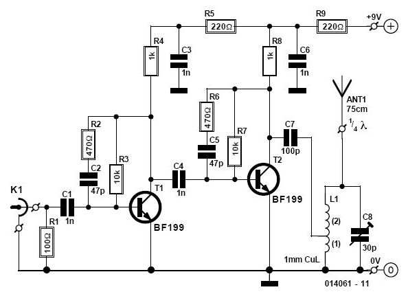
Booster for Cable Radio
This circuit enables the use of a portable VHF FM radio to receive audio from stations that exclusively broadcast on the local cable network.
This circuit operates by modulating the audio signals from the local cable network onto a carrier frequency...

Schematics VHF FM Receiver TDA7000 88-108 MHz
The 10K resistor is necessary if the receiver is to mute (squelch) under no-signal conditions. An additional 100K resistor can be added in series with this resistor to create an adjustable squelch. This circuit is designed to drive a crystal...

VHF FM Transmitter MAX2606
To achieve independence from local radio stations when testing VHF receivers, a frequency-modulated oscillator is required that operates within the range of 89.5 to 108 MHz. However, constructing such an oscillator using discrete components can be quite challenging. Maxim has...

2 Watt VHF linear amplifier
Once again my collection of projects creation has been interrupted by another necessity. Patrick and other people have asked me for a circuit of a VHF power amplifier. These circuits are my "standard" building blocks that can be used to...

VHF FM transmitter
I have had requests to add a VHF FM transmitter, to the QRP collection. This project is a simple transmitter using only one crystal and will cover 145.00 to 146.00 MHz. The crystal is a 44.9333 MHz crystal for 145.500...
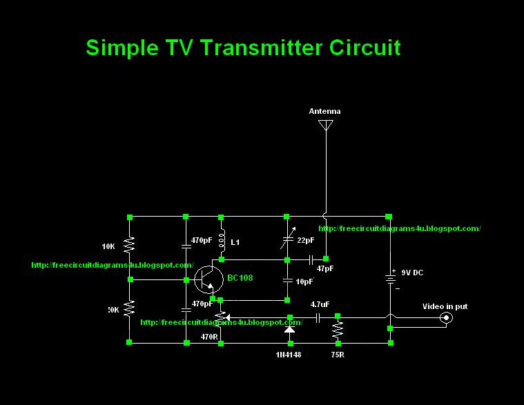
TV Transmitter circuit diagram (VHF)
Many individuals inquire about TV transmitters. This document provides a useful circuit diagram that enables signal transmission over distances of 75 to 100 meters. The circuit diagram is not original; it was provided by a friend. Contributions of circuit diagrams...

Period-To-Voltage Converter
The input signal drives the ICD. Because the positive input (V+) of the ICD is slightly offset to +0.1 V, its steady-state output will be around +13 V. This voltage is sent to the ICC through D2, which sets the...

VHF Antenna Amplifier Circuit Using BFT66 Transistor
This design presents a simple antenna amplifier electronic circuit project, which can be utilized based on the provided circuit diagram. The antenna amplifier operates effectively within a frequency range of 1 to 300 MHz. It is suitable for high frequency...
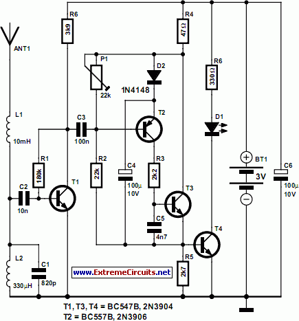
Thunderstorm Predictor
Listening to VHF FM offers significant advantages over MW/LW AM, providing clear stereo sound that is free from interference, fading, and noise.
VHF FM (Very High Frequency Frequency Modulation) is a radio transmission method that operates in the frequency range of...