


1w fm booster based 2n4427
#FM booster
#RF amplifier
#2N4427
#transistor
#linear amplifier
#small fm transmitters
#BGY133
#BLY87
#power supply
#12V

Description: This circuit diagram illustrates a linear FM booster and RF amplifier utilizing the Philips 2N4427 transistor. The RF amplifier is designed to enhance the performance of small FM transmitters and bugs, employing two Philips 2N4427 transistors, delivering approximately 1 Watt of output power. The output stage can drive any linear amplifier such as the BGY133 or BLY87. The power supply should provide a current of 500mA at 12 Volts. While higher voltage can extend transmission distance, it risks damaging the transistors if exceeded beyond 15 Volts. The amplifier offers a gain of 15 dB within the frequency range of 80 MHz to 110 MHz. Inductors L4, L5, and L6 are constructed as 5mm diameter air coils with 8 turns, using 1mm diameter wire. This project is relatively straightforward but yields impressive results.
The circuit operates on the principle of amplifying RF signals, making it suitable for applications in FM transmission. The use of two 2N4427 transistors in a push-pull configuration enhances the overall gain and efficiency of the amplifier. The transistors are capable of handling the power requirements while maintaining linearity, which is critical for FM signals to avoid distortion.
The design specifies a power supply of 12 Volts, with a recommended current rating of 500mA, ensuring that the circuit operates within safe limits. Exceeding the voltage beyond 15 Volts is cautioned against, as it can lead to thermal runaway and eventual failure of the transistors. The amplifier's gain of 15 dB is optimal for boosting signals in the specified frequency range, which is particularly useful for FM broadcasting applications.
The inductors L4, L5, and L6 play a crucial role in tuning the amplifier to the desired frequency range. These air-core coils, constructed with 1mm wire, provide the necessary inductance while minimizing losses associated with core materials. The choice of 8 turns for each coil is a balance between size and inductance, ensuring compactness without compromising performance.
This circuit can be assembled on a standard PCB, with attention to layout to minimize parasitic inductance and capacitance. Proper grounding techniques and decoupling capacitors are recommended to ensure stable operation. Overall, this FM booster circuit is an effective solution for enhancing the range and clarity of FM transmission, making it a valuable project for electronics enthusiasts and professionals alike.This is the circuit diagram of linear FM Booster / RF amplifier based 2N4427 Philips transistor. The RF Amplifier is for boosting small fm transmitters and bugs. It use two Philips 2N4427 and its power is about 1Watt. At the output you can drive any linear with BGY133 or BLY87 and so on. Its power supply has to give 500mA current at 12 Volts. More voltage can boost the distance but the transistors will be burned much earlier than usual. ! In any case do not exceed the 15Volts. The Amp offers 15 dB in the area of 80Mhz to 110 Mhz. L4, L5, and L6 are 5mm diameter air coils, 8 turns, with wire 1mm wire diameter. This is an easy project, but will give you great results.
The circuit operates on the principle of amplifying RF signals, making it suitable for applications in FM transmission. The use of two 2N4427 transistors in a push-pull configuration enhances the overall gain and efficiency of the amplifier. The transistors are capable of handling the power requirements while maintaining linearity, which is critical for FM signals to avoid distortion.
The design specifies a power supply of 12 Volts, with a recommended current rating of 500mA, ensuring that the circuit operates within safe limits. Exceeding the voltage beyond 15 Volts is cautioned against, as it can lead to thermal runaway and eventual failure of the transistors. The amplifier's gain of 15 dB is optimal for boosting signals in the specified frequency range, which is particularly useful for FM broadcasting applications.
The inductors L4, L5, and L6 play a crucial role in tuning the amplifier to the desired frequency range. These air-core coils, constructed with 1mm wire, provide the necessary inductance while minimizing losses associated with core materials. The choice of 8 turns for each coil is a balance between size and inductance, ensuring compactness without compromising performance.
This circuit can be assembled on a standard PCB, with attention to layout to minimize parasitic inductance and capacitance. Proper grounding techniques and decoupling capacitors are recommended to ensure stable operation. Overall, this FM booster circuit is an effective solution for enhancing the range and clarity of FM transmission, making it a valuable project for electronics enthusiasts and professionals alike.This is the circuit diagram of linear FM Booster / RF amplifier based 2N4427 Philips transistor. The RF Amplifier is for boosting small fm transmitters and bugs. It use two Philips 2N4427 and its power is about 1Watt. At the output you can drive any linear with BGY133 or BLY87 and so on. Its power supply has to give 500mA current at 12 Volts. More voltage can boost the distance but the transistors will be burned much earlier than usual. ! In any case do not exceed the 15Volts. The Amp offers 15 dB in the area of 80Mhz to 110 Mhz. L4, L5, and L6 are 5mm diameter air coils, 8 turns, with wire 1mm wire diameter. This is an easy project, but will give you great results.

G STRAIN ENERGY ABSORBER
It is important to know that transistors Q1, Q2, Q3 must not work like an astable (tri-phase) multivibrator (you could verify it on scope (no square waves but NON LINEAR wave between XB, YB, ZB must be displayed on the...

-15 V 1-A Regulated Power Supply
The supply receives -20 V from the rectifier/filter which is fed to the collector of the Darlington pnp pass transistor, a TIP105. The base drive to the TIP105 is supplied through resistor R5. The base of the TIP is driven...

power supply circuit
The SheevaPlug is known to have a suboptimal power supply, particularly affecting users in the UK operating at 240VAC. Additionally, heavy loads on the USB can cause issues, especially when connecting an external mechanical disk drive. This project aims to...

60 WATTS LINEAR AMPLIFIER
The 60 Watt linear amplifier is a simple all solid state circuit using power mosfet IRF840. The IRF series of power transistors are available in various voltage and power ratings. A single IRF840 can handle a maximum power output of...

12Vdc Mobile Battery Charger
This circuit provides an output of up to 20 V from a 12-V automotive supply, enabling constant current charging of NiCad battery assemblies with a total voltage of approximately 18 V. The circuit utilizes a square-wave oscillator (VI) and diodes...

12 Volt Car Battery Charger Circuit Schematic
Unlike many units, this battery charger continuously charges at maximum current, tapering off only near full battery voltage. In this unit, the full load.
This battery charger is designed to operate with a continuous charging mechanism, maintaining the maximum current output...
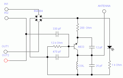
A933 Transistor Telephone Listening
The following circuit illustrates the A933 Transistor Telephone Listening Circuit Diagram. Features include the ability to tune from 88 to approximately 94 MHz and a simple design.
The A933 Transistor Telephone Listening Circuit is designed to function as a radio frequency...

Vehicle Detector
A simple single-transistor Colpitts oscillator is depicted in the schematic. When a vehicle passes over the loop, the inductance decreases, resulting in an increase in the oscillator frequency. A microprocessor measures the oscillator frequency and takes appropriate actions based on...

Transistorized flashers
Transistors Q1 and Q2 are configured as a free-running multivibrator. The output at the emitter of Q2 drives the base of the common emitter amplifier Q3, which controls the lamp. This circuit configuration allows for independent variation of flash duration,...