


220Mhz Receiving Converter
#220MHz
#144MHz
#receiver
#converter
#transistor
#mixer
#RF
#frequency conversion
#single transistor

Description: A simple circuit utilizing a single transistor converts 220 MHz to 144 MHz or vice versa, as the mixer is bilateral. The transformer has 15 turns on the primary and 2 turns on the secondary (#24 AWG wire) on a 0.375" ID SF-material toroidal coil.
The described circuit serves as a frequency converter, capable of shifting signals between 220 MHz and 144 MHz, which can be particularly useful in radio frequency applications. The core component of this circuit is a single transistor that functions as a mixer, allowing for bidirectional signal conversion due to its bilateral nature.
The transformer used in this circuit is critical for the conversion process. It consists of a primary winding with 15 turns and a secondary winding with 2 turns, both wound with #24 AWG wire. The choice of wire gauge and the number of turns are essential for achieving the desired impedance transformation and frequency response characteristics. The use of a toroidal core made from SF material (Silicon Ferrite) provides a compact and efficient magnetic structure that minimizes losses and enhances performance at high frequencies.
In terms of operation, the circuit can accept an input signal at one frequency and produce an output signal at the other frequency. This is achieved by mixing the input signal with a local oscillator signal within the transistor, generating the desired frequency output. The design's simplicity allows for ease of implementation, while the careful selection of components ensures reliable operation across the specified frequency range.
Overall, this circuit exemplifies a straightforward yet effective approach to frequency conversion in RF applications, demonstrating the utility of basic electronic components in achieving complex signal processing tasks. A simple circuit using a single transistor converts 220 MHz to 144 MHz or vice versa, because the mixer is bila teral. Tl has 15 turns on the primary, and 2 turns on the secondary (#24 AWG wire) on a 0.375" ID SF-material toroidal coil.
The described circuit serves as a frequency converter, capable of shifting signals between 220 MHz and 144 MHz, which can be particularly useful in radio frequency applications. The core component of this circuit is a single transistor that functions as a mixer, allowing for bidirectional signal conversion due to its bilateral nature.
The transformer used in this circuit is critical for the conversion process. It consists of a primary winding with 15 turns and a secondary winding with 2 turns, both wound with #24 AWG wire. The choice of wire gauge and the number of turns are essential for achieving the desired impedance transformation and frequency response characteristics. The use of a toroidal core made from SF material (Silicon Ferrite) provides a compact and efficient magnetic structure that minimizes losses and enhances performance at high frequencies.
In terms of operation, the circuit can accept an input signal at one frequency and produce an output signal at the other frequency. This is achieved by mixing the input signal with a local oscillator signal within the transistor, generating the desired frequency output. The design's simplicity allows for ease of implementation, while the careful selection of components ensures reliable operation across the specified frequency range.
Overall, this circuit exemplifies a straightforward yet effective approach to frequency conversion in RF applications, demonstrating the utility of basic electronic components in achieving complex signal processing tasks. A simple circuit using a single transistor converts 220 MHz to 144 MHz or vice versa, because the mixer is bila teral. Tl has 15 turns on the primary, and 2 turns on the secondary (#24 AWG wire) on a 0.375" ID SF-material toroidal coil.

Transistor common emitter amplifier circuit
The circuit is a bias circuit for automatic stabilizers that maintains a stable quiescent operating point with good thermal stability. It utilizes a three-pole tube with an NPN type transistor, characterized by a small Iceo. An adjustment potentiometer, RP, is...

Radio circuits built
This receiver is a modification of Charles Wenzel's Two Transistor Reflex Radio. Instead of a ferrite AM loopstick antenna, a magnetic loop antenna is used, and an LM386 amplifier stage has been added to drive an 8-ohm speaker. A switch...

Receiver-Interface Circuit For Preamps Circuit
The purpose of the receiver/interface circuit is to pass RF to the receiver through capacitor C9, while adding DC power to the feedline through resistor R2 and RF choke L7.
The receiver/interface circuit is designed to facilitate the transmission of radio...

80M And 40M Cw-Ssb Receiver Circuit
This direct-conversion receiver utilizes a TDA7000 integrated circuit (IC) and incorporates an LM386 audio amplifier. The TDA7000 serves as the mixer and local oscillator (L.O.) section. The frequency control can be achieved using either an air variable capacitor or a...

Leaky Transistor Buffer
The wah pedal operates before the amplifier but produces a low volume and a scratchy sound when the pedal is rocked back and forth. It functions correctly without the buffer. When placed in front of a Fuzz Face, no sound...

Simple Intercom Circuit Transistor
The circuit diagram represents a simple yet effective intercom system entirely based on transistors. It consists of three stages along with an RC amplifier. When the pushbutton S2 is pressed, the amplifier circuit around transistor T1 is activated.
The intercom circuit...

One transistor audio mixer (2N3563)
This circuit mixer features internal amplification using a 2N3563 transistor. Two input signals can be independently adjusted via VRI and VR2. The VR3 balance control allows for the attenuation of one signal while the other remains active. Additionally, the transistor...

Portable Mixers
Portable mixer with a high-quality modular design. Powered by a 9V battery, it features very low current consumption. The device integrates a preamplifier, tone control, and mixer functionalities into a single unit, making it an ideal electronics project. Circuit diagram...
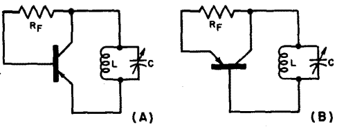
Fundamentals of Transistor Oscillators
This chapter discusses the operation and circuitry of transistor oscillators, which can be categorized into two types: feedback (similar to vacuum tube oscillators) and negative-resistance (current multiplying). Transistor oscillators can generate sine waves using various operational modes, including some novel...