


2SC2539 FM RF Amplifier
#FM broadcast
#RF amplifier
#2SC2539
#VHF band
#power amplifier
#transistor
#silicon NPN
#epitaxial planar
#RF power
#VHF

Description: This FM broadcast RF amplifier is constructed using the 2SC2539, which is a silicon NPN epitaxial planar type transistor designed for RF power amplifiers in the VHF band.
The FM broadcast RF amplifier utilizing the 2SC2539 transistor operates effectively within the VHF frequency range, making it suitable for various applications in radio broadcasting. The 2SC2539 is known for its high gain and efficiency, which are critical parameters in RF amplification.
The circuit typically consists of a few key components: the 2SC2539 transistor, biasing resistors, coupling capacitors, and a power supply. The biasing resistors are essential for establishing the correct operating point of the transistor, ensuring it operates in the active region for linear amplification. Coupling capacitors are used to block DC while allowing the RF signal to pass through, maintaining signal integrity.
In addition, an output matching network may be included to optimize the power transfer from the transistor to the antenna, enhancing the overall performance of the amplifier. The design must consider factors such as load impedance and frequency response to achieve the desired output power and signal quality.
Proper heat dissipation measures, such as heat sinks, are also critical in maintaining the reliability of the 2SC2539 during operation, as RF amplifiers can generate significant heat. Overall, the design of this FM broadcast RF amplifier is a balance of component selection, circuit topology, and thermal management to achieve optimal performance in VHF applications.This FM broadcast rf amplifier is built with 2SC2539 which is a silicon NPN epitaxal planar type transistor designed for RF power amplifiers in VHF band mo..
The FM broadcast RF amplifier utilizing the 2SC2539 transistor operates effectively within the VHF frequency range, making it suitable for various applications in radio broadcasting. The 2SC2539 is known for its high gain and efficiency, which are critical parameters in RF amplification.
The circuit typically consists of a few key components: the 2SC2539 transistor, biasing resistors, coupling capacitors, and a power supply. The biasing resistors are essential for establishing the correct operating point of the transistor, ensuring it operates in the active region for linear amplification. Coupling capacitors are used to block DC while allowing the RF signal to pass through, maintaining signal integrity.
In addition, an output matching network may be included to optimize the power transfer from the transistor to the antenna, enhancing the overall performance of the amplifier. The design must consider factors such as load impedance and frequency response to achieve the desired output power and signal quality.
Proper heat dissipation measures, such as heat sinks, are also critical in maintaining the reliability of the 2SC2539 during operation, as RF amplifiers can generate significant heat. Overall, the design of this FM broadcast RF amplifier is a balance of component selection, circuit topology, and thermal management to achieve optimal performance in VHF applications.This FM broadcast rf amplifier is built with 2SC2539 which is a silicon NPN epitaxal planar type transistor designed for RF power amplifiers in VHF band mo..

4 watt 900mhz rf amplifier
This RF amplifier circuit delivers a power output of 4 Watts at a frequency of 900 MHz. It utilizes Wilkinson power dividers in the base and collector circuits of transistors Q2 and Q3. Two SD1853 driver application transistors are paralleled...

RF amplifier and filter for 144 MHz
The RF amplifiers utilize noiseless feedback through the drain-gate capacitance, incorporating an inductor in the source lead to achieve the necessary 90-degree phase shift between the gate voltage and channel current. The first RF amplifier provides approximately 4 dB of...

Transistor phase shift oscillator. RC phase shift network and RC phase shift oscillator using opap
Transistor RC phase shift oscillator. RC phase shift oscillator using operational amplifier. RC phase shift network. Theory and working principle. Circuit diagram.
The transistor RC phase shift oscillator is a type of electronic oscillator that generates sine wave signals. This oscillator...

Controlled Transistor Series Regulator With Overload and Short-Circuit Protection
If the load resistance (RL) is reduced or the load terminals are accidentally shorted, a very large load current will flow, potentially damaging the pass transistor (Q1), diode, or other components. Fuse protection may not be sufficient, as the transistor...

vhf antenna amplifier
The PCB of this circuit should be positioned close to the antenna within a compact metallic enclosure. This VHF antenna circuit requires a 12 volts DC power supply, which can be sourced from a 12-volt battery, as the current consumption...

RF amplifier circuit 1W 2.3GHz MRF2001
RF amplifier circuit diagram, delivering 1W for 2.3GHz, built based on MRF2001. This RF amplifier provides approximately 1 Watt power output with a minimum gain of 8 dB at a 24V voltage supply. The frequency can be tuned from 2.25GHz...

Simple Cable TV Amplifier Circuit
This cable TV amplifier circuit is an RF amplifier designed for quick installation between two coaxial cables. Both the input and output impedances are compatible with 75-ohm cables. The main amplifier is the T1 transistor, while T2 functions as an...

low noise vhf uhf oscillators
Unlike conventional small-signal methods, employing large-signal, time-domain design techniques facilitates the creation of low-noise grounded-base oscillators suitable for VHF/UHF applications.
The development of low-noise grounded-base oscillators for VHF/UHF applications presents unique challenges and opportunities. By utilizing large-signal, time-domain design techniques, engineers...
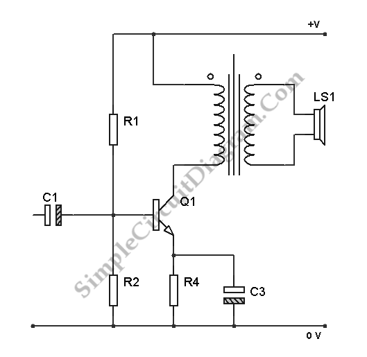
Transistor Class A Power Amplifier
The transistor is biased in Class A, meaning that the collector current flows continuously. This current can vary, increasing or decreasing in response to the input signal.
In a Class A biasing configuration, the transistor operates in the active region for...