


3.5 To 10Mhz Simple Superheterodyne Receiver

Description: In this circuit, U1 is a frequency converter that supplies the 455-kHz intermediate frequency (IF) stage U2 and detector U3. U4 serves as the audio output stage. R9 functions as a gain control, allowing for the adjustment of the gain of U2. Coil data is provided in the parts list. R6 and R7 are 10k ohm resistors, while R9 is a 10k ohm potentiometer. T1 and T2 are 10.7 MHz microminiature (7mm) IF transformers, with Mouser part number 42IF223 for the green core and T3 and T4 are 455 kHz microminiature (7mm) IF transformers, with Mouser part number 42IF203 for the black core. U1 and U3 are NE602 double-balanced mixers, U2 is an MC3340 variable attenuator, U4 is an LM380N-8 audio amplifier, and U5 is a 78L05 100 mA miniature +5V regulator. Capacitors C10 and C11 can range from 0.1 to 0.22 µF, with values greater than 0.33 µF causing distortion. Additional components include printed stripboard (DSE PN H5614 or equivalent), a cabinet, plastic stick-on feet, and 4-40 hardware.
The circuit operates primarily as a radio frequency (RF) signal processing unit, converting incoming RF signals into audio output. The frequency converter U1 takes an RF input and down-converts it to a 455 kHz IF signal, which is then processed by U2, the variable attenuator. The gain control resistor R9 allows for fine-tuning the output level of the IF stage, ensuring optimal performance based on varying signal strengths.
The NE602 mixers (U1 and U3) are integral to the conversion process, providing high selectivity and low distortion, essential for maintaining signal integrity. The audio output stage, using the LM380N-8, amplifies the processed audio signal for output. The use of microminiature transformers (T1, T2, T3, and T4) minimizes space while allowing for efficient signal coupling between stages.
Capacitors C10 and C11 play a critical role in filtering and stabilizing the circuit. The specified range of capacitance values is crucial to prevent distortion, particularly in audio applications. A printed stripboard is utilized for assembly, providing a compact and efficient layout for the components, while the plastic stick-on feet and 4-40 hardware ensure a secure and stable installation.
Overall, this circuit is designed for effective signal processing in radio frequency applications, balancing size, performance, and ease of assembly. In this circuit, Ul is a frequency converter that feeds the 455-kHz IF stage U2 and detector U3. U4 is the audio output stage. R9 is a gain control that varies the gain of U2. Coil data is given in the part list. R6, R710k, YiWcarbon composition R910kpotentiometer T1, T210.7 MHzmicrominiature (7mm)Mouser PN 42IF223 IF transformer, green core T3,T4455 kHzmicrominiature (7mm)Mouser PN 42IF203 IF transformer, black core U1, U3NE602double-balanced mixer U2MC3340variable attenuator U4LM380N-8audio amplifier U578L05100 mA miniature+5V regulator * C10 and C11 can range from 0.1 to 0.22. Valves greater than 0.33 cause distortion. Other: Printed stripboard, DSE PN H5614 or equivalent, cabinet, plastic stick-on feet, 4-40 hardware, etc.
The circuit operates primarily as a radio frequency (RF) signal processing unit, converting incoming RF signals into audio output. The frequency converter U1 takes an RF input and down-converts it to a 455 kHz IF signal, which is then processed by U2, the variable attenuator. The gain control resistor R9 allows for fine-tuning the output level of the IF stage, ensuring optimal performance based on varying signal strengths.
The NE602 mixers (U1 and U3) are integral to the conversion process, providing high selectivity and low distortion, essential for maintaining signal integrity. The audio output stage, using the LM380N-8, amplifies the processed audio signal for output. The use of microminiature transformers (T1, T2, T3, and T4) minimizes space while allowing for efficient signal coupling between stages.
Capacitors C10 and C11 play a critical role in filtering and stabilizing the circuit. The specified range of capacitance values is crucial to prevent distortion, particularly in audio applications. A printed stripboard is utilized for assembly, providing a compact and efficient layout for the components, while the plastic stick-on feet and 4-40 hardware ensure a secure and stable installation.
Overall, this circuit is designed for effective signal processing in radio frequency applications, balancing size, performance, and ease of assembly. In this circuit, Ul is a frequency converter that feeds the 455-kHz IF stage U2 and detector U3. U4 is the audio output stage. R9 is a gain control that varies the gain of U2. Coil data is given in the part list. R6, R710k, YiWcarbon composition R910kpotentiometer T1, T210.7 MHzmicrominiature (7mm)Mouser PN 42IF223 IF transformer, green core T3,T4455 kHzmicrominiature (7mm)Mouser PN 42IF203 IF transformer, black core U1, U3NE602double-balanced mixer U2MC3340variable attenuator U4LM380N-8audio amplifier U578L05100 mA miniature+5V regulator * C10 and C11 can range from 0.1 to 0.22. Valves greater than 0.33 cause distortion. Other: Printed stripboard, DSE PN H5614 or equivalent, cabinet, plastic stick-on feet, 4-40 hardware, etc.

Wireless video camera link
This high-performance video camera link transmits signals from a video camera to a VCR or from a VCR to TVs throughout a home. The initial stage of the RF chain features a crystal-controlled oscillator, Q1, operating at a frequency range...

Superheterodyne Radio Uses One Tube
This project is based on modifications of existing circuits, primarily inspired by Jack Bryant's one-tube superheterodyne contest radio project. The circuit design was influenced by valuable suggestions from fellow radio enthusiasts Ben Tongue and Mike Peebles. The radio is constructed...

Field Strength Meter
This circuit is a wideband signal strength meter designed to respond to small variations in RF energy within the VHF spectrum. It is capable of detecting AM or FM modulation as well as a simple carrier wave. The circuit measures...
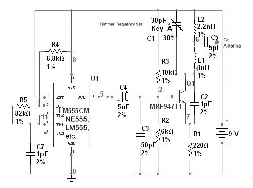
radio station blocker circuit
This device functions as a reversal of a radio station, sending a null signal to a selected frequency to eliminate the actual broadcast. The radio transmitter operates at a loss of 10,000W; therefore, this circuit is intended for use only...

100 MHz RF oscillator with ATtiny12
A frequency reference for tuning up the RS-232 to 100 MHz RF desktop channel adapter elsewhere on this site, when I found this Saronix crystal oscillator in my junk box. A few minutes with AVRStudio produced an ATtiny12 to make...

Tuned Rf Wavemeter
L1 and L2 form a tuned transformer with an optimum turns ratio of approximately 1:3. L2 and C1 are used to tune to the desired frequency. The frequency range can extend from 10 kHz to over 200 MHz, depending on...

Bandswitched Grid Dip Meter
This circuit is designed for checking resonances in tuned circuits, antennas, and similar applications, covering a frequency range of 2 to 20 MHz. Q1 acts as an oscillator that can be tuned across this range using capacitor C1 and band-switched...

RF Dummy load
The load described here is capable of handling up to 10 watts of RF power for a couple of minutes and is designed for the widely used 50 ohms impedance. It consists of ten parallel connected 560 ohms 1 watt...

6 Channel RF Remote Control
This project creates a simple but valuable wireless remote controller. It has as many as 6 channels (a rare feature for remote control devices) and transmits encoded MM53200, UM3750, or UM86409. Of course, you can omit the button and make...