


40 meter band Receiver II

Description: Using the circuit of 40-metre band direct-conversion receiver described here, one can listen to amateur radio QSO signals in CW as well as in SSB mode in the 40-metre band. The circuit makes use of three n-channel FETs (BFW10). The first FET (T1) performs the function of ant./RF amplifier-cum-product detector, while the second and third FETs (T2 and T3) together form a VFO (variable frequency oscillator) whose output is injected into the gate of first FET (T1) through 10pF capacitor C16. The VFO is tuned to a frequency which differs from the incoming CW signal frequency by about 1 kHz to produce a beat frequency in the audio range at the output of transformer X1, which is an audio driver transformer of the type used in transistor radios. The audio output from transformer X1 is connected to the input of audio amplifier built around IC1 (TBA820M) via volume control VR1. An audio output from the AF amplifier is connected to an 8-ohm, 1-watt speaker. The receiver can be powered by a 12-volt power-supply, capable of sourcing around 250mA current. Audio-output stage can be substituted with a readymade L-plate audio output circuit used in transistor amplifiers, if desired. The necessary data regarding the coils used in the circuit is given in the circuit diagram itself.
The 40-metre band direct-conversion receiver circuit is designed to effectively receive and demodulate amateur radio signals, utilizing a straightforward architecture that integrates n-channel FETs for enhanced performance. The first FET (T1) serves as both an antenna and RF amplifier, enhancing the weak incoming signals. The configuration allows for the detection of both Continuous Wave (CW) and Single Sideband (SSB) signals, making it versatile for various communication modes.
The VFO, formed by the second and third FETs (T2 and T3), is crucial in generating a local oscillator signal that is slightly offset from the incoming CW signal frequency. This offset, typically around 1 kHz, enables the production of an audible beat frequency at the output. The coupling of the VFO output to T1 through a 10pF capacitor (C16) ensures that the oscillator frequency can be finely tuned, which is essential for effective signal demodulation.
The output from T1 is routed through transformer X1, which is specifically chosen for its audio driver capabilities. This transformer converts the RF signals into audio frequencies suitable for further amplification. The audio signal is then fed into an audio amplifier circuit built around the TBA820M IC, allowing for volume control via the variable resistor (VR1). The final audio output is designed to drive an 8-ohm speaker, providing clear audio reproduction of the received signals.
Powering the circuit requires a 12-volt power supply with a current capacity of approximately 250mA, ensuring that all components operate within their specified limits. For those seeking an alternative output stage, a standard L-plate audio output circuit can be employed, providing flexibility in design and implementation. The circuit diagram includes detailed specifications for the coils used, which are critical for the proper functioning of the receiver. This comprehensive design facilitates amateur radio enthusiasts in effectively receiving and enjoying communications within the 40-metre band. Using the circuit of 40-metre band direct-conversion receiver descr- ibed here, one can listen to amateur radio QSO signals in CW as well as in SSB mode in the 40-metre band. The circuit makes use of three n-channel FETs (BFW10). The first FET (T1) performs the function of ant./RF amplifier-cum-product detector, while the second and third FETs (T2 and T3) together form a VFO (variable frequency oscillator) whose output is injected into the gate of first FET (T1) through 10pF capacitor C16.
The VFO is tuned to a frequency which differs from the incoming CW signal frequency by about 1 kHz to produce a beat frequency in the audio range at the output of transformer X1, which is an audio driver transformer of the type used in transistor radios. The audio output from transformer X1 is connected to the input of audio amplifier built around IC1 (TBA820M) via volume control VR1. An audio output from the AF amplifier is connected to an 8-ohm, 1-watt speaker. The receiver can be powered by a 12-volt power-supply, capable of sourcing around 250mA current. Audio-output stage can be substituted with a readymade L-plate audio output circuit used in transistor amplifiers, if desired.
The necessary data regarding the coils used in the circuit is given in the circuit diagram itself.
The 40-metre band direct-conversion receiver circuit is designed to effectively receive and demodulate amateur radio signals, utilizing a straightforward architecture that integrates n-channel FETs for enhanced performance. The first FET (T1) serves as both an antenna and RF amplifier, enhancing the weak incoming signals. The configuration allows for the detection of both Continuous Wave (CW) and Single Sideband (SSB) signals, making it versatile for various communication modes.
The VFO, formed by the second and third FETs (T2 and T3), is crucial in generating a local oscillator signal that is slightly offset from the incoming CW signal frequency. This offset, typically around 1 kHz, enables the production of an audible beat frequency at the output. The coupling of the VFO output to T1 through a 10pF capacitor (C16) ensures that the oscillator frequency can be finely tuned, which is essential for effective signal demodulation.
The output from T1 is routed through transformer X1, which is specifically chosen for its audio driver capabilities. This transformer converts the RF signals into audio frequencies suitable for further amplification. The audio signal is then fed into an audio amplifier circuit built around the TBA820M IC, allowing for volume control via the variable resistor (VR1). The final audio output is designed to drive an 8-ohm speaker, providing clear audio reproduction of the received signals.
Powering the circuit requires a 12-volt power supply with a current capacity of approximately 250mA, ensuring that all components operate within their specified limits. For those seeking an alternative output stage, a standard L-plate audio output circuit can be employed, providing flexibility in design and implementation. The circuit diagram includes detailed specifications for the coils used, which are critical for the proper functioning of the receiver. This comprehensive design facilitates amateur radio enthusiasts in effectively receiving and enjoying communications within the 40-metre band. Using the circuit of 40-metre band direct-conversion receiver descr- ibed here, one can listen to amateur radio QSO signals in CW as well as in SSB mode in the 40-metre band. The circuit makes use of three n-channel FETs (BFW10). The first FET (T1) performs the function of ant./RF amplifier-cum-product detector, while the second and third FETs (T2 and T3) together form a VFO (variable frequency oscillator) whose output is injected into the gate of first FET (T1) through 10pF capacitor C16.
The VFO is tuned to a frequency which differs from the incoming CW signal frequency by about 1 kHz to produce a beat frequency in the audio range at the output of transformer X1, which is an audio driver transformer of the type used in transistor radios. The audio output from transformer X1 is connected to the input of audio amplifier built around IC1 (TBA820M) via volume control VR1. An audio output from the AF amplifier is connected to an 8-ohm, 1-watt speaker. The receiver can be powered by a 12-volt power-supply, capable of sourcing around 250mA current. Audio-output stage can be substituted with a readymade L-plate audio output circuit used in transistor amplifiers, if desired.
The necessary data regarding the coils used in the circuit is given in the circuit diagram itself.
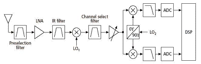
receiver architectures
Various architectures of receivers have been proposed in literature, but the most popular architectures among them, such as Heterodyne, Homodyne, Wideband-IF, and Low-IF, are presented here.
The Heterodyne receiver architecture utilizes two frequencies: the incoming radio frequency (RF) signal and a...
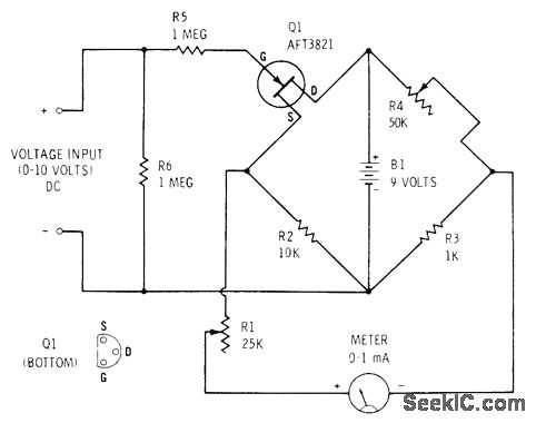
FET VOLTMETER
A Field Effect Transistor (FET) is incorporated into one leg of a Wheatstone bridge, resulting in a meter with an input impedance exceeding 1 megohm. To achieve a zero reading on the meter when no input voltage is present, R4...

10 watt rf amplifier for 18mhz by
This project aims to provide a 0.55-watt input that can easily be amplified to a 10-watt output. The two linear amplifiers are designed for use with QRP SSB/CW/FM/AM transmitters on the amateur bands of 15 and 17 meters and can...

60watt rf radio frequency
The 60 Watt RF (Radio Frequency) Amplifier is a simple all-solid-state design utilizing the MOSFET IRF840. The IRF series of power transistors are available in various voltage and power ratings. A single IRF840 can handle a maximum power output of...

Wideband RF Amplifier
This circuit consists of wideband RF amplifiers that utilize current-feedback components such as the THS3202. The THS3202 was selected for its fast slew rate and wide bandwidth. The amplifier voltage gain of this circuit is 20, while the stage voltage...

TV signal amplifier 470Mhz-860Mhz
This amplifier is designed to amplify RF signals from an antenna by 10 dB and operates as a Class A amplifier using the BFQ34 transistor from Philips. The BFQ34 is packaged in an SOT122A case. The BFQ34T variant is available...
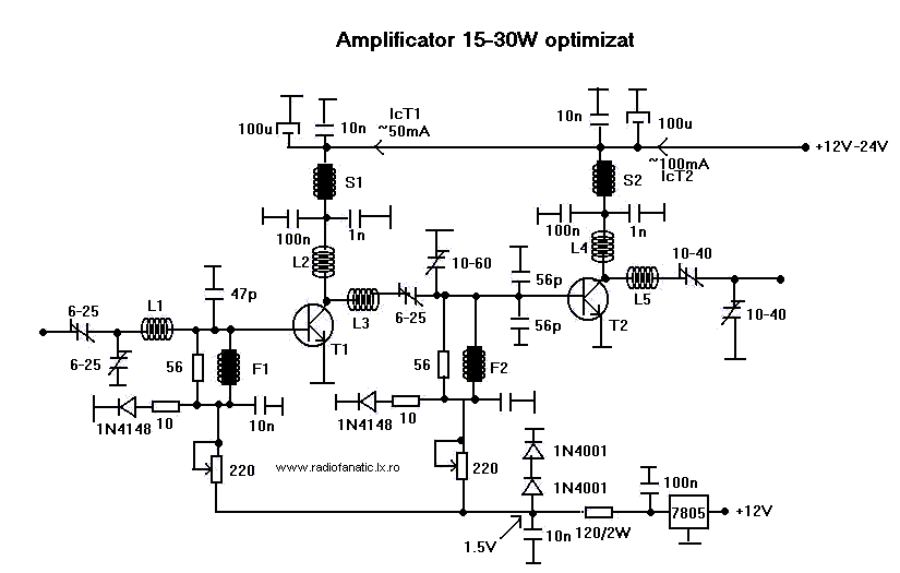
15W - 30W RF Power Amplifier KT922 KT930 KT934
This RF amplifier ensures the power required to boost a small transmitter. Depending on the input RF power, power supply, and transistor, this amplifier can boost the signal.
The RF amplifier is a critical component in various communication systems, designed to...

Used in conjunction with multimeters FET Vp Vas checker
Chen is in the operational amplifier circuit, utilizing a feedback loop with input resistance that determines the current roll-off. The FET drain current is controlled by the determination circuit, which provides the necessary voltage. The output constitutes a fake blood...

tv power amplifier schematic
TV RF Power Amplifier 14W. This RF power amplifier operates within the frequency range of 470 - 860 MHz, covering UHF Band IV and V, and delivers an output power of 14 Watts with an input power of 1.5 Watts....