


42 Mc Band to 88 Mc Band (retrofit converter) Project
#FM radio
#frequency converter
#retrofit
#RF circuit
#wire winding
#vintage electronics
#signal conversion
#band conversion
#Radio Age

Description: Before World War II the FM radio band was just below 50 Mc. Read all about it. If you have such a radio, you might want to build this converter. It will let your old set receive the modern FM band (88 to 108 Mc.). This design is based on an article I wrote for Radio Age. You must wind L1 yourself. Use any cylindrical object that is just under 1/2 inch in diameter. I used a thick pencil from my son’s grade school class, but a magic marker or a large drill bit will work just fine. Wind 6 turns with #18 or #20 wire. Wind the wire tightly on the cylinder and then slip the wire off.
The described circuit serves as a frequency converter that allows vintage FM radios, originally designed to operate on frequencies below 50 MHz, to receive the modern FM band ranging from 88 to 108 MHz. This is particularly relevant for users who wish to enhance the capabilities of older radio equipment without replacing the entire unit.
The primary component of the converter is an inductor, referred to as L1, which must be manually constructed by the user. The specifications for L1 require it to be wound with either #18 or #20 gauge wire, which provides an adequate balance between resistance and inductance for radio frequency applications. The recommended cylindrical form for winding L1 should have a diameter slightly less than 1/2 inch. Common household items, such as a thick pencil, a magic marker, or a large drill bit, can be utilized to create the necessary winding form.
The winding process involves creating six tight turns of wire around the chosen cylindrical object. It is crucial to ensure that the wire is wound tightly to maintain consistent inductance and performance. Once the winding is complete, the wire should be carefully slipped off the form to maintain the integrity of the inductor shape.
In addition to L1, the circuit may include other passive components, such as resistors and capacitors, to form a complete frequency conversion system. The circuit would typically include a mixer stage to combine the input RF signal with a local oscillator signal, generating an intermediate frequency that can be easily amplified and filtered.
This converter design allows older radios to access a broader range of FM stations, thereby preserving the functionality of vintage equipment in the modern broadcasting landscape. Proper assembly and tuning of the circuit are essential to ensure optimal performance and reception quality.Before World War II the FM radio band was just below 50 Mc. Read all about it. If you have such a radio, you might want to build this converter. It will let your old set receive the modern FM band (88 to 108 Mc.). This design is based on an article I wrote for Radio Age. You must wind L1 yourself. Use any cylindrical object that is just under 1/2 inch in diameter. I used a thick pencil from my son`s grade school class, but a magic marker or a large drill bit will work just fine. Wind 6 turns with #18 or #20 wire. Wind the wire tightly on the cylinder and then slip the wire off.
The described circuit serves as a frequency converter that allows vintage FM radios, originally designed to operate on frequencies below 50 MHz, to receive the modern FM band ranging from 88 to 108 MHz. This is particularly relevant for users who wish to enhance the capabilities of older radio equipment without replacing the entire unit.
The primary component of the converter is an inductor, referred to as L1, which must be manually constructed by the user. The specifications for L1 require it to be wound with either #18 or #20 gauge wire, which provides an adequate balance between resistance and inductance for radio frequency applications. The recommended cylindrical form for winding L1 should have a diameter slightly less than 1/2 inch. Common household items, such as a thick pencil, a magic marker, or a large drill bit, can be utilized to create the necessary winding form.
The winding process involves creating six tight turns of wire around the chosen cylindrical object. It is crucial to ensure that the wire is wound tightly to maintain consistent inductance and performance. Once the winding is complete, the wire should be carefully slipped off the form to maintain the integrity of the inductor shape.
In addition to L1, the circuit may include other passive components, such as resistors and capacitors, to form a complete frequency conversion system. The circuit would typically include a mixer stage to combine the input RF signal with a local oscillator signal, generating an intermediate frequency that can be easily amplified and filtered.
This converter design allows older radios to access a broader range of FM stations, thereby preserving the functionality of vintage equipment in the modern broadcasting landscape. Proper assembly and tuning of the circuit are essential to ensure optimal performance and reception quality.Before World War II the FM radio band was just below 50 Mc. Read all about it. If you have such a radio, you might want to build this converter. It will let your old set receive the modern FM band (88 to 108 Mc.). This design is based on an article I wrote for Radio Age. You must wind L1 yourself. Use any cylindrical object that is just under 1/2 inch in diameter. I used a thick pencil from my son`s grade school class, but a magic marker or a large drill bit will work just fine. Wind 6 turns with #18 or #20 wire. Wind the wire tightly on the cylinder and then slip the wire off.
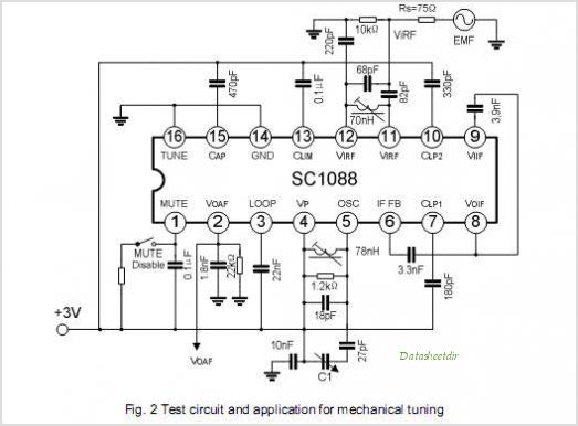
SC1088 AUTO SEARCH TUNING FM RADIO RECEIVER
The SC1437 is a battery overvoltage detection circuit that includes a driver for an external MOSFET. The trip point can be adjusted using an external resistor divider connected to the SENSE pin. If no external divider is used, the trip...

Bi-Level Squelch
The proper operation of the squelch circuit in any FM radio is essential to avoid listening to discriminator noise. This is particularly critical in a repeater system. The primary function of a squelch circuit is to detect the presence of...

The application circuit of TDA7088 FM integrated circuit
This is the schematic diagram for an automatic search FM radio. The primary component is the TDA7088 integrated circuit, which encompasses the FM radio receiver, antenna, oscillator, mixer, automatic frequency control (AFC) circuit, intermediate frequency amplifier (with an IF frequency...

VOLTAGE TO FREQUENCY CONVERTER + 1uS LED PULSE DRIVER
This circuit receives the signal from the amplifier and emits powerful 1μs infrared light pulses from a low-cost LED, which are frequency modulated by the audio information. The 10kHz center frequency of the pulse stream is sufficiently low, allowing a...

FM Radio Receiver using TDA7088
This compact receiver is slightly larger than an AA battery. It is powered by two LR44 button cells, which are relatively costly and may not have a long lifespan. There is an intention to search for LR44 batteries at local...

CXA1019 FM Radio
CXA1019 FM RADIO CXA1019 is a one-chip FM/AM radio IC designed for radio-cassette tape recorders and headphone tape recorders, and CXA1019S has the...
The CXA1019 is an integrated circuit (IC) specifically engineered for FM/AM radio applications, particularly within radio-cassette tape recorders...

TDA7000 fm radio integrated circuit design
The TDA7000 features a Frequency-Locked-Loop (FLL) system with an intermediate frequency of 70 kHz, and selectivity is achieved through active RC filters. The only calibration required is for the resonant circuit associated with the oscillator, which is necessary for the...

TEA5764UK TEA5764UK FM Radio + RDS
The TK10931V is an intermediate frequency (IF) integrated circuit that incorporates two IF systems—one designated for frequency modulation (FM) and the other for amplitude modulation (AM)—along with a detector. This device is suitable for use in amateur radios, CB radios,...

simple home made fm radio receiver
L1 and L2 were constructed by wrapping three tight loops side by side around a Sharpie marker. L2 was additionally created by wrapping approximately 8 inches of 35 AWG magnet wire around a ferrite core, ensuring that the windings were...