


4W FM Transmitters
#FM transmitter
#RF circuit
#inductor
#resistor
#aerial
#parallel circuit
#voice transmission
#radio

Description: L2 RFC (resistance 1MΩ with an inductor wrapped around it consisting of several coils made from fine insulated wire. The inductor is connected in parallel with the resistance, forming a parallel L-R circuit.) With capacitors C7 and C8, the resistance of the aerial is adjusted (practically, they are regulated to ensure our voice is heard on the radio as clearly as possible).
The described circuit features an L2 RFC (Radio Frequency Choke) with a resistance value of 1MΩ. The inductor, constructed from multiple turns of fine insulated wire, is designed to provide inductance while minimizing losses at radio frequencies. The parallel configuration of the resistor and inductor allows for effective filtering and impedance matching in RF applications.
The inclusion of capacitors C7 and C8 serves to further fine-tune the circuit. These capacitors can be used to create a resonant circuit with the inductor, enhancing the performance of the aerial (antenna) by optimizing the frequency response. This adjustment is crucial for ensuring that the audio signal, specifically the voice, is transmitted clearly over the radio waves.
In practical applications, the values of C7 and C8 may be adjusted to achieve the desired resonance frequency, which is essential for effective communication. The circuit's design emphasizes the importance of both inductive and capacitive elements in achieving optimal performance in RF transmission, highlighting the interplay between resistance, inductance, and capacitance in radio frequency circuits.L2 RFC (resistance 1MOhm with wrapped around her inductor of enough coils from fine isolated wire. Scratch of utmost inductor and you stick in utmost the resistance making thus a parallel L-r circuit. ) With their C7, C8 we adapt the resistance of aerial (practically to them we regulate so that it is heard our voice in the radio as long as you become cleaner).
The described circuit features an L2 RFC (Radio Frequency Choke) with a resistance value of 1MΩ. The inductor, constructed from multiple turns of fine insulated wire, is designed to provide inductance while minimizing losses at radio frequencies. The parallel configuration of the resistor and inductor allows for effective filtering and impedance matching in RF applications.
The inclusion of capacitors C7 and C8 serves to further fine-tune the circuit. These capacitors can be used to create a resonant circuit with the inductor, enhancing the performance of the aerial (antenna) by optimizing the frequency response. This adjustment is crucial for ensuring that the audio signal, specifically the voice, is transmitted clearly over the radio waves.
In practical applications, the values of C7 and C8 may be adjusted to achieve the desired resonance frequency, which is essential for effective communication. The circuit's design emphasizes the importance of both inductive and capacitive elements in achieving optimal performance in RF transmission, highlighting the interplay between resistance, inductance, and capacitance in radio frequency circuits.L2 RFC (resistance 1MOhm with wrapped around her inductor of enough coils from fine isolated wire. Scratch of utmost inductor and you stick in utmost the resistance making thus a parallel L-r circuit. ) With their C7, C8 we adapt the resistance of aerial (practically to them we regulate so that it is heard our voice in the radio as long as you become cleaner).

0,4 Watt FM transmitter
Power supply: 12-14 V stab., 100 mA. RF power: 400 mW. Impedance: 50-75 ohm. Frequency range: 87.5-108 MHz. Modulation: wideband FM. Connect the 6 V / 0.1 A bulb to the output and use R1 to tune the right frequency....

SV3 Radio Magnadyne Radio
Most models produced in the 1930s utilize similar circuits, particularly in the RF section, which follows a common LW-MW-SW scheme. Variations among different models primarily stem from the inclusion or exclusion of variable selectivity control, the sophistication of tone controls,...

Spy Telephone
This FM spy telephone circuit is connected in series with the phone line. When there is a signal on the wires, this transmitter will radiate airwaves through the wires, which act as an antenna. There is no need for batteries...

4W FM Transmitter
4W FM Transmitter. Technical Characteristics: Stabilized power supply: Vcc = 12~16V. Emission frequency: 88~108MHz. Current consumption: 100~400mA.
The 4W FM transmitter is designed to operate within a frequency range of 88 to 108 MHz, which is the standard FM broadcast...

200mW High Quality FM Transmitter With TX-200
The TX200 is an advanced and significantly larger VFO/VCO FM transmitter, recognized as one of the best transmitters available. It is a 200mW FM transmitter designed for stereo PLL applications, providing a wide range for broadcasting music throughout a home...

TW-42 FM radio transmitter high-frequency amplifier circuit section
The FM radio transmitter is a high-frequency amplifier circuit that utilizes the Mitsubishi frequency set, specifically the M57704H discharge path. It operates within the frequency range of 457-458 MHz and has a transmission power of 5 watts. As illustrated in...
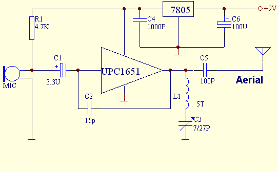
UPC1651 FM Transmitter
This FM transmitter is built with UPC1651, which is a silicon monolithic integrated circuit specifically designed as a wideband amplifier covering the HF band.
The UPC1651 is a versatile integrated circuit that serves as a key component in FM transmitter designs,...

FM Crystal Controlled Transmitter DPT
The DPT Transmitter is a dual-powered voice transmitter designed to operate in two modes: a high-power mode for long-range transmission and a low-power mode for extended battery life. It functions at a low power level of 100 mW and a...

FM Transmitter (2N2222)
This circuit is a simple two transistor (2N2222) FM transmitter. No license is required for this transmitter according to FCC regulations regarding wireless microphones. If powered by a 9-volt battery and used with an antenna no longer than 12 inches,...