


500mW FM transmitter
#FM transmitter
#VHF amplifier
#modulator
#oscillator
#LED power meter
#88-108 MHz
#low power
#audio transmission
#battery powered

Description: The TX500 is a simple to build 500mW FM Transmitter. It consists of three blocks: modulator/oscillator, two-stage 500mW VHF amplifier, and LED-based power meter. The TX500 allows transmitting audio signals to the FM band at frequencies from 88 MHz to 108 MHz. Due to the very low power consumption of less than 100mA, the circuit may be perfectly powered by using a 9-12V battery or power supply if preferred. The circuit has been divided into separate stages so that it is better for everyone to understand how every part works independently. The carrier frequency of an oscillator is determined by the capacity of C4, C5 in conjunction with the inductance of the coil L1. 3.5 turns are needed and 27pF for C5 to tune to a lower part of the FM band (88-100MHz). To be able to tune to a higher part (100...
The TX500 FM transmitter circuit is designed to operate efficiently within the FM broadcast band, allowing for audio transmission with a maximum output power of 500mW. The circuit is modular, comprising three main functional blocks: the modulator/oscillator, a dual-stage VHF amplifier, and an LED-based power meter, which provides visual feedback on the output power level.
The modulator/oscillator block generates the carrier frequency, which is crucial for FM transmission. The frequency is adjustable and can be set between 88 MHz and 108 MHz, making it compatible with standard FM radio receivers. The tuning of the oscillator is achieved through the combination of capacitors C4 and C5 and the inductance of the coil L1. Specifically, the oscillator requires 3.5 turns of wire for L1, with a capacitance of 27pF for C5 to effectively tune the circuit to the lower part of the FM band (88-100 MHz). This tunability is essential for compliance with local broadcasting regulations and to avoid interference with existing FM stations.
The VHF amplifier consists of two amplification stages, which increase the output power to the desired level while maintaining signal integrity. This design ensures that the transmitted signal is strong enough to be received clearly over a reasonable distance without significant distortion. The amplifier stages are carefully designed to operate with minimal power consumption, drawing less than 100mA, which allows for the use of portable power sources such as a 9-12V battery.
Lastly, the LED-based power meter provides a convenient method for users to monitor the transmitter's output power in real-time. This feature is particularly useful for ensuring the transmitter operates within safe limits and for making adjustments as necessary.
Overall, the TX500 is a well-structured FM transmitter that balances performance with ease of construction, making it suitable for hobbyists and educational purposes alike. Its modular design enhances understanding of radio frequency circuits by allowing users to study each component's function independently.The TX500 is a simple to build 500mW FM Transmitter. It consists of three blocks; modulator / oscillator, two stage 500mW VHF amplifier and LED based power meter. The TX500 allows to transmit audio signals to FM band at frequencies from 88 MHz to 108 MHz. Due to the very low power consumption of less than 100mA the circuit may be perfectly powered by using 9-12V battery or power supply if you prefer.
The circuit has been divided into separate stages so that it is be better for everyone to understand how every part works independently. The carrier frequency of an oscillator is determined by the capacity of C4, C5 in conjunction with the inductance of the coil L1. 3.5 turns are needed and 27pF for C5 to tune to a lower part of FM band (88-100MHz). To be able to tune to a higher part (100
The TX500 FM transmitter circuit is designed to operate efficiently within the FM broadcast band, allowing for audio transmission with a maximum output power of 500mW. The circuit is modular, comprising three main functional blocks: the modulator/oscillator, a dual-stage VHF amplifier, and an LED-based power meter, which provides visual feedback on the output power level.
The modulator/oscillator block generates the carrier frequency, which is crucial for FM transmission. The frequency is adjustable and can be set between 88 MHz and 108 MHz, making it compatible with standard FM radio receivers. The tuning of the oscillator is achieved through the combination of capacitors C4 and C5 and the inductance of the coil L1. Specifically, the oscillator requires 3.5 turns of wire for L1, with a capacitance of 27pF for C5 to effectively tune the circuit to the lower part of the FM band (88-100 MHz). This tunability is essential for compliance with local broadcasting regulations and to avoid interference with existing FM stations.
The VHF amplifier consists of two amplification stages, which increase the output power to the desired level while maintaining signal integrity. This design ensures that the transmitted signal is strong enough to be received clearly over a reasonable distance without significant distortion. The amplifier stages are carefully designed to operate with minimal power consumption, drawing less than 100mA, which allows for the use of portable power sources such as a 9-12V battery.
Lastly, the LED-based power meter provides a convenient method for users to monitor the transmitter's output power in real-time. This feature is particularly useful for ensuring the transmitter operates within safe limits and for making adjustments as necessary.
Overall, the TX500 is a well-structured FM transmitter that balances performance with ease of construction, making it suitable for hobbyists and educational purposes alike. Its modular design enhances understanding of radio frequency circuits by allowing users to study each component's function independently.The TX500 is a simple to build 500mW FM Transmitter. It consists of three blocks; modulator / oscillator, two stage 500mW VHF amplifier and LED based power meter. The TX500 allows to transmit audio signals to FM band at frequencies from 88 MHz to 108 MHz. Due to the very low power consumption of less than 100mA the circuit may be perfectly powered by using 9-12V battery or power supply if you prefer.
The circuit has been divided into separate stages so that it is be better for everyone to understand how every part works independently. The carrier frequency of an oscillator is determined by the capacity of C4, C5 in conjunction with the inductance of the coil L1. 3.5 turns are needed and 27pF for C5 to tune to a lower part of FM band (88-100MHz). To be able to tune to a higher part (100

2 Transistor FM Voice Transmitters
This circuit can be adjusted to operate within the frequency range of 87-108 MHz, achieving a transmission distance of approximately 20 to 30 meters. The design incorporates a pair of BC548 transistors, which, while not specifically designated as RF transistors,...
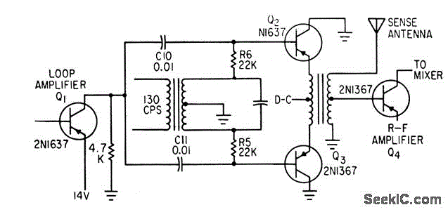
BALANCED MODULATOR FOR ADF
Combines signals from loop and sense antennas of an automatic direction finder to produce a 130-cps output with the correct phase for driving the rotor of a resolver to achieve a null position.
The circuit described is integral to the operation...

Oscillator-clock generator
This self-starting fixed frequency oscillator circuit provides excellent frequency stability. R1 and C1 form the frequency-determining network, while R2 supplies regenerative feedback. Diode D1 improves stability by compensating for the difference between Voh and Vsupply. In applications requiring a precision...

Two Transistors FM Transmitter
This circuit is a radio frequency (RF) oscillator that operates around 100 MHz. The audio is picked up and amplified by the electret.
The RF oscillator circuit described operates at a frequency of approximately 100 MHz, making it suitable for various...

fm transmitter colpitt oscillator
C1 takes the DC-decoupled voltage from the microphone, amplifies it via Q1, then C2 decouples it again. R6 and C3 form a low-pass filter, but once the signal reaches Q2, the circuit accomplishes frequency modulation. The frequency deviation is achieved...

Wide frequency oscillator
An oscillator/amplifier is resistively tunable over a wide frequency range. Feedback circuits containing operational amplifiers, resistors, and capacitors synthesize the electrical effects of inductance and capacitance in parallel between the input terminals. The synthetic inductance and capacitance, and therefore the...

1W FM Transmitter Circuit
A highly effective 1-watt FM transmitter circuit that is easy to construct. The circuit consists of four transistors: one functions as a stable oscillator, followed by a buffer stage to maintain frequency stability during adjustments. Next is a resonance stage,...

VHF-band FM Circuit of Variable Capacitance Diode
The circuit functions as a frequency modulation (FM) transmitter that operates within the 76 to 90 MHz FM radio band, commonly referred to as a wireless microphone. It receives signals through an FM radio receiver. The circuit is capable of...

Marker-generator
The oscillator section employs three sections of a 7400 quad NAND gate integrated circuit. The 1 MHz signal generated by the oscillator is input into a 7490 decade counter, which is configured to divide by ten, producing a 100 kHz...