


6W Morse-Code Transmitter 7Mhz Circuit
#Morse-code
#transmitter
#7Mhz
#vacuum tube
#CW transmitter
#breadboard
#hookup wire
#ballast resistor

Description: The vacuum tube remains relevant and functional in certain applications, such as in this continuous wave (CW) transmitter. The circuit is constructed in a traditional breadboard style on a wooden base. Old table radios serve as a valuable source of components for this circuit. V3 acts as a ballast resistor, which can be replaced with a 75- or 100-ohm, 5-watt resistor. L1 consists of 15 turns of hookup wire wound on a 2-inch form. Additionally, L2 is composed of 7 turns of the same wire and is wound over L1. Caution is advised as voltages up to 160 V are present on Y1 and V2.
The CW transmitter circuit utilizes vacuum tubes, which are known for their ability to amplify signals and operate at high voltages. The design employs a wooden base to support the breadboard layout, allowing for easy modifications and adjustments. The use of components salvaged from old table radios not only promotes recycling but also provides cost-effective solutions for building the circuit.
In the circuit, V3 serves as a ballast resistor, which is crucial for stabilizing the current and ensuring consistent operation of the vacuum tube. The choice of a 75- or 100-ohm, 5-watt resistor allows for flexibility in sourcing components while maintaining the desired electrical characteristics.
Inductors L1 and L2 play a significant role in the circuit's operation. L1, with its 15 turns of hookup wire, is designed to provide the necessary inductance for the circuit's frequency requirements. The 2-inch form used for winding L1 ensures that the inductor maintains a compact size while achieving the desired electrical performance. L2, with 7 turns wound over L1, acts as a coupling inductor, enhancing the circuit's efficiency by transferring energy between stages effectively.
Safety precautions are paramount, particularly due to the presence of high voltages (up to 160 V) on components Y1 and V2. Proper insulation and careful handling are essential to prevent electrical shock and ensure safe operation of the transmitter. Overall, this CW transmitter circuit exemplifies the enduring utility of vacuum tubes in modern electronics, showcasing their application in RF transmission while emphasizing the importance of safety and component sourcing. The vacuum tube is still alive and useful in some applications, as in this CW transmitter, The circuit was built in old-fashioned breadboard style on a wooden base. Old table radios are a good source of parts for this circuit. V3 is used as a ballast resistora 75- or 100- 5-W resistor could be substituted. LI is 15 turns of hookup wire on a form 2 long. L2 is 7 turns of the same wire. L2 is wound over LI. Be careful as up to 160 V is present onYl and V2.
The CW transmitter circuit utilizes vacuum tubes, which are known for their ability to amplify signals and operate at high voltages. The design employs a wooden base to support the breadboard layout, allowing for easy modifications and adjustments. The use of components salvaged from old table radios not only promotes recycling but also provides cost-effective solutions for building the circuit.
In the circuit, V3 serves as a ballast resistor, which is crucial for stabilizing the current and ensuring consistent operation of the vacuum tube. The choice of a 75- or 100-ohm, 5-watt resistor allows for flexibility in sourcing components while maintaining the desired electrical characteristics.
Inductors L1 and L2 play a significant role in the circuit's operation. L1, with its 15 turns of hookup wire, is designed to provide the necessary inductance for the circuit's frequency requirements. The 2-inch form used for winding L1 ensures that the inductor maintains a compact size while achieving the desired electrical performance. L2, with 7 turns wound over L1, acts as a coupling inductor, enhancing the circuit's efficiency by transferring energy between stages effectively.
Safety precautions are paramount, particularly due to the presence of high voltages (up to 160 V) on components Y1 and V2. Proper insulation and careful handling are essential to prevent electrical shock and ensure safe operation of the transmitter. Overall, this CW transmitter circuit exemplifies the enduring utility of vacuum tubes in modern electronics, showcasing their application in RF transmission while emphasizing the importance of safety and component sourcing. The vacuum tube is still alive and useful in some applications, as in this CW transmitter, The circuit was built in old-fashioned breadboard style on a wooden base. Old table radios are a good source of parts for this circuit. V3 is used as a ballast resistora 75- or 100- 5-W resistor could be substituted. LI is 15 turns of hookup wire on a form 2 long. L2 is 7 turns of the same wire. L2 is wound over LI. Be careful as up to 160 V is present onYl and V2.
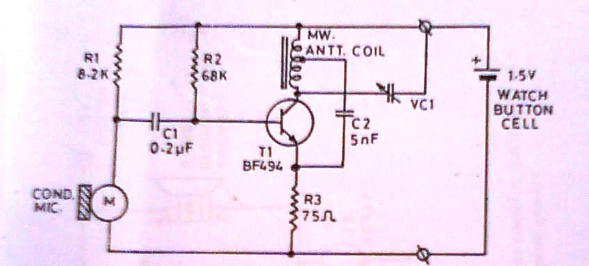
ultra miniature transmitter
This transmitter is approximately the size of a large coat button. It accepts direct voice input and operates on a single watch-type button cell, providing several tens of hours of use. The schematic illustrates that this transmitter is likely the...

Simple Short-Wave Transmitter
This low-cost short-wave transmitter is tunable from 10 to 15 MHz using a ½J gang condenser VC1, which sets the carrier frequency in conjunction with inductor L1. Frequency trimming is achieved with VC2. The carrier signal is amplified by transistor...

CW Transmitter
This one-valve (ECL82) CW Transmitter occupies a very special place in my amateur radio history. I was first licensed in 1994 but did not operate on air. I committed to only ever operate equipment which I had made myself. I...

integrated vacuum tube amp
The only schematic of this amplifier known is the one obtained from Song at Canadian HiFi Online.
The schematic in question represents the electronic configuration of a specific amplifier model. This schematic is crucial for understanding the circuit's operation, including the...

radio mf tx
There has been a longstanding interest in constructing a simple VXO transmitter, though concerns regarding the limited tuning range typically associated with VXOs on busy HF bands have been present. The capability to switch between multiple crystals and cover various...
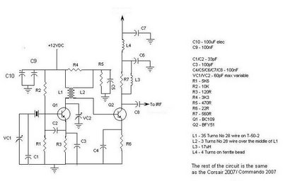
Corsair and Commando TXs
This document provides information about the Corsair and Commando Transmitters designed by Dave Martin of WNKR. It outlines the construction of each transmitter and includes examples created by others. The circuit diagram presented illustrates the initial two stages of a...
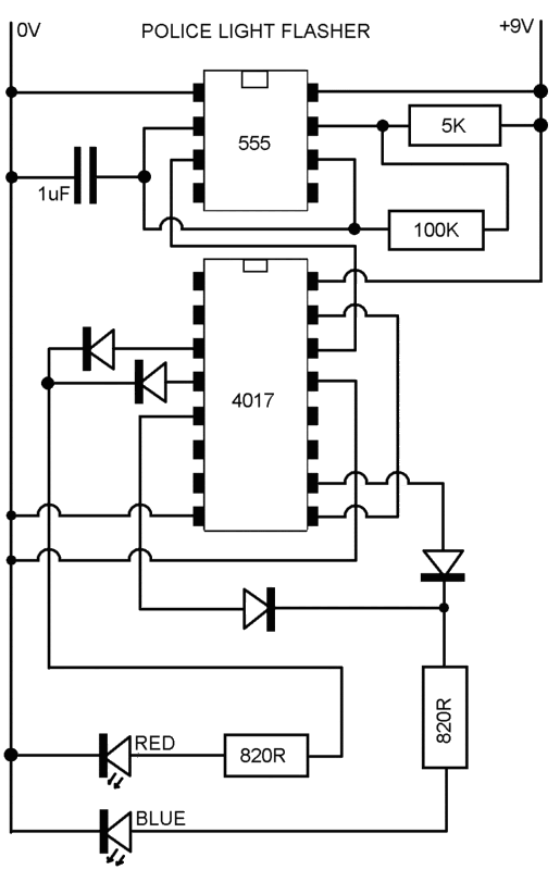
Simple breadboard project with my 6 year old
A six-year-old child and an adult viewed a project on YouTube and captured an image of it using the print screen function to create a similar design.
The project likely involves a basic electronic circuit that can be replicated easily, providing...

valved transmitter for 3.5 MHz
This transmitter project is a highly efficient, rugged, and simple low-power continuous wave (C.W.) unit delivering more than 10W. It is crystal-controlled with stabilized high tension (H.T.) and features a buffer stage between the crystal oscillator and power amplifier stages,...

Three ECC83-Based Tube Phono Preamplifier Circuits
The three circuits were based on the vacuum tube ECC83, designed to produce phono preamplifiers in compliance with RIAA standards.
The described circuits utilize the ECC83 vacuum tube, a dual-triode component known for its low noise and high gain characteristics, making...