


88-108 Mhz to AM broadcast band
#FM tuner
#AM radio
#frequency conversion
#RF circuit
#broadcast band
#88-108 MHz
#signal conversion
#radio receiver
#tuner circuit

Description: I designed this circuit. It can be connected to an FM tuner to play FM stations on an AM radio.
This circuit serves as an interface between an FM tuner and an AM radio, allowing the reception of FM stations on an AM band. The design typically includes a modulator that converts the frequency of the FM signal into a format that can be transmitted over the AM band.
The circuit may consist of the following key components:
1. **FM Tuner**: The FM tuner receives the desired FM radio frequency. It often includes a front end that filters and amplifies the incoming signal to ensure clarity and strength.
2. **Modulator**: This component is crucial as it converts the FM signal into an AM signal. A common approach is to use a product modulator or a balanced modulator that mixes the FM signal with a carrier frequency, which is typically set within the AM band.
3. **Carrier Oscillator**: This oscillator generates the carrier frequency that the modulator uses. The frequency is adjustable, allowing the user to select a specific AM channel for transmission.
4. **Amplifier**: After modulation, the AM signal may require amplification to ensure it can be effectively transmitted over the airwaves. A Class C amplifier is often used for this purpose due to its efficiency in broadcasting.
5. **Antenna**: The output signal is then transmitted via an antenna designed for AM frequencies. This antenna should be carefully designed to match the impedance of the amplifier to maximize power transfer.
6. **Power Supply**: A stable power supply is necessary to provide the required voltage and current to the circuit components, ensuring reliable operation.
In summary, this circuit effectively bridges the gap between FM and AM radio technologies, enabling users to enjoy FM broadcasts on standard AM receivers. Proper tuning and alignment of the components are essential for optimal performance and signal quality.I designed this circuit. It can be connected to an FM tuner to play FM stations on an AM radio.
This circuit serves as an interface between an FM tuner and an AM radio, allowing the reception of FM stations on an AM band. The design typically includes a modulator that converts the frequency of the FM signal into a format that can be transmitted over the AM band.
The circuit may consist of the following key components:
1. **FM Tuner**: The FM tuner receives the desired FM radio frequency. It often includes a front end that filters and amplifies the incoming signal to ensure clarity and strength.
2. **Modulator**: This component is crucial as it converts the FM signal into an AM signal. A common approach is to use a product modulator or a balanced modulator that mixes the FM signal with a carrier frequency, which is typically set within the AM band.
3. **Carrier Oscillator**: This oscillator generates the carrier frequency that the modulator uses. The frequency is adjustable, allowing the user to select a specific AM channel for transmission.
4. **Amplifier**: After modulation, the AM signal may require amplification to ensure it can be effectively transmitted over the airwaves. A Class C amplifier is often used for this purpose due to its efficiency in broadcasting.
5. **Antenna**: The output signal is then transmitted via an antenna designed for AM frequencies. This antenna should be carefully designed to match the impedance of the amplifier to maximize power transfer.
6. **Power Supply**: A stable power supply is necessary to provide the required voltage and current to the circuit components, ensuring reliable operation.
In summary, this circuit effectively bridges the gap between FM and AM radio technologies, enabling users to enjoy FM broadcasts on standard AM receivers. Proper tuning and alignment of the components are essential for optimal performance and signal quality.I designed this circuit. It can be connected to an FM tuner to play FM stations on an AM radio.

AM Radio
A MW AM radio like those you buy, or used to buy. Use just BC549 trannies, with the BC559 complement being allowed in the audio output stage. Buying RF antenna coils, oscillator coils and intermediate frequency transformers would be cheating...

Sine to Square Wave Converter
This schematic example demonstrates a sinusoidal voltage input at a frequency of 10 kHz, which is converted to a square wave using an inverter-based circuit. The VDD and VSS rails are connected to +1V and -1V, respectively. The control file...

Simple AM radio
This is a straightforward AM radio circuit utilizing only two transistors. The coil L1 and variable capacitor C1 create the tank circuit. Transistor Q1 is responsible for demodulation, and the demodulated signal is accessible at the base of Q1. This...

Build Basic Radio Frequency Electronic Circuits
AM radio receivers demodulate amplitude-modulated (AM) signals. The primary source of these signals is the Standard AM Radio Broadcast Band, although shortwave stations also utilize AM modulation. Amplitude modulation was developed between 1900 and 1917 by amateur radio enthusiasts. Following...

AM Radio Receiver Circuit Using TDA 1072AT IC
The TDA1072AT is a specialized integrated circuit designed for AM radio receivers, produced by Philips Semiconductors. This IC is intended for use in both mains-fed home receivers and car radios. It features a voltage-controlled oscillator that delivers signals with exceptionally...
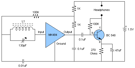
am radio receiver with mk484
This schematic illustrates a high-quality AM radio receiver circuit centered around the MK484 AM radio integrated circuit (IC). The MK484 is known for its high sensitivity and superior performance, featuring only three leads and housed in a TO-92 package. It...

Radio receiver GEOLOG circuit diagram
To enhance usability during nighttime, the receiver features a scale with bias lighting, and the surface behind the scale is coated with a fluorescent material. To activate the scale illumination, press button 3. Radio programs can be listened to through...
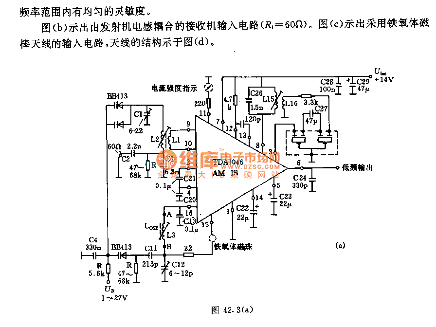
IC AM radio circuit
The receiver input circuit is powered by a 60Ω generator. A low-pass filter is employed to permit the entire frequency range while maintaining uniform sensitivity. The receiver input circuit is coupled with a transmitter inductive component (Ri = 60Ω). Additionally,...

5 Tube AC/DC Radio Receiver
Nearly all AM radio manufacturers utilized this specific circuit from approximately 1948 to 1963. There is a growing interest in collecting these radios as antiques. Credit for the creator of this figure and caption is sought, but the source of...