


Aerial BoosterCircuit for Citizens Band Project
#aerial booster
#Citizen Band
#RF amplifier
#signal booster
#CB radio
#antenna
#transmitter
#receiver
#RF circuit
#hobby project

Description: This simple aerial booster circuit design could serve as an alternative or a hobby project for creating an aerial booster device for Citizen Band (CB) radio.
The aerial booster circuit is designed to enhance the performance of Citizen Band (CB) radios by increasing the effective range and improving signal clarity. The circuit typically consists of a few critical components, including a power supply, a transistor amplifier, and an antenna matching network.
The power supply provides the necessary voltage and current to the circuit. A common choice is a 12V DC power supply, which is readily available and can be sourced from car batteries or dedicated power adapters.
The transistor amplifier is the heart of the aerial booster, responsible for amplifying the weak signals received by the antenna. Typically, a low-noise transistor such as the 2N3904 or a similar NPN transistor is used for this purpose. The transistor is configured in a common-emitter configuration to achieve significant voltage gain.
The antenna matching network is crucial for ensuring that the impedance of the antenna matches that of the booster circuit. This matching prevents signal reflection, which can lead to loss of signal strength. Components such as inductors and capacitors are used to create a matching network that optimizes the performance of the antenna at the desired frequency range for CB radio, typically around 27 MHz.
Additional components may include resistors for biasing the transistor, capacitors for coupling and bypassing, and possibly a variable potentiometer for tuning the circuit to achieve the best performance.
This aerial booster circuit can be assembled on a protoboard or printed circuit board (PCB) for durability and ease of use. Proper shielding and grounding techniques should be employed to minimize interference from external sources, which can degrade the performance of the booster.
Overall, this circuit design offers an accessible way for hobbyists and enthusiasts to enhance their CB radio experience, allowing for clearer communications over greater distances.This simple aerial booster circuit design might be an alternate or a hobby project for making such an aerial booster device for the Citizen Band (CB) radio
The aerial booster circuit is designed to enhance the performance of Citizen Band (CB) radios by increasing the effective range and improving signal clarity. The circuit typically consists of a few critical components, including a power supply, a transistor amplifier, and an antenna matching network.
The power supply provides the necessary voltage and current to the circuit. A common choice is a 12V DC power supply, which is readily available and can be sourced from car batteries or dedicated power adapters.
The transistor amplifier is the heart of the aerial booster, responsible for amplifying the weak signals received by the antenna. Typically, a low-noise transistor such as the 2N3904 or a similar NPN transistor is used for this purpose. The transistor is configured in a common-emitter configuration to achieve significant voltage gain.
The antenna matching network is crucial for ensuring that the impedance of the antenna matches that of the booster circuit. This matching prevents signal reflection, which can lead to loss of signal strength. Components such as inductors and capacitors are used to create a matching network that optimizes the performance of the antenna at the desired frequency range for CB radio, typically around 27 MHz.
Additional components may include resistors for biasing the transistor, capacitors for coupling and bypassing, and possibly a variable potentiometer for tuning the circuit to achieve the best performance.
This aerial booster circuit can be assembled on a protoboard or printed circuit board (PCB) for durability and ease of use. Proper shielding and grounding techniques should be employed to minimize interference from external sources, which can degrade the performance of the booster.
Overall, this circuit design offers an accessible way for hobbyists and enthusiasts to enhance their CB radio experience, allowing for clearer communications over greater distances.This simple aerial booster circuit design might be an alternate or a hobby project for making such an aerial booster device for the Citizen Band (CB) radio
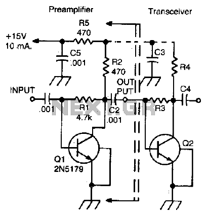
Two-meter preamplifier
This simple, inexpensive, wideband RF amplifier provides 14 dB gain on two meters without the use of tuned circuits.
The RF amplifier described operates within the two-meter band, which typically spans frequencies from 144 to 148 MHz. It is designed to...

10.7 MHz RF Amplifier And Filter
The following circuit illustrates a 10.7 MHz RF amplifier and filter circuit diagram. Features include significant capacitances of a power MOSFET.
The 10.7 MHz RF amplifier and filter circuit is designed to amplify radio frequency signals while simultaneously filtering out unwanted...

Broadcast Band Rf Amplifier Circuit
The circuit features a frequency response that spans from 100 Hz to 3 MHz, with a gain of approximately 30 dB. Field-effect transistor Q1 is arranged in a common-source self-biased configuration, and an optional resistor R1 is available to adjust...

1 Watt Linear RF Amplifier
The RF circuit is a C-Class power amplifier. It is used in the last stage of transmitters. Its maximum power output is about 1 Watt. The circuit can be used in 3 frequency ranges: 30-100-200 MHz. More: The P-Out column...

The R2 Single Sideband Direct Conversion Receiver
The old common-base audio preamp, which has a noise figure of 5 dB, is a clear candidate for improvement in noise performance. A common-emitter configuration with shunt feedback provides an input resistance of 50 ohms, which is preferred by the...

Antenna Low Power RF & Wireless Connectivity
The "green area" is designated for the placement of the TRF7970A's antenna, which should be connected between two 0-ohm resistors. The antenna can be constructed step by step following the guidelines in the document "Antenna Matching for the TRF7960 RFID...
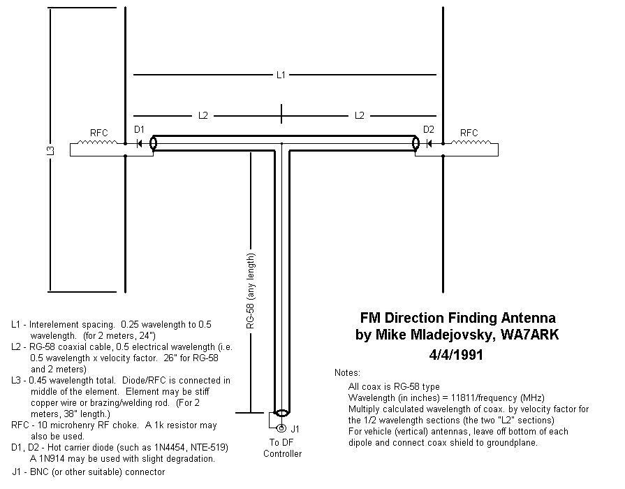
Two Homing type Direction-Finding
The antenna consists of two vertical dipoles. Diodes in each dipole allow the circuit to select which antenna is active at any given time. When a positive voltage is sent up the coax feedline, diode D1 conducts and D2 blocks,...

Remote Control Transmitter Circuit
This transmitter can be utilized for multiple applications. An INS8048L microprocessor produces various codes based on keypad inputs. These codes are modulated onto a 40-kHz carrier frequency. Additionally, Q1 drives infrared LEDs LED1 and LED2.
The transmitter circuit primarily consists of...
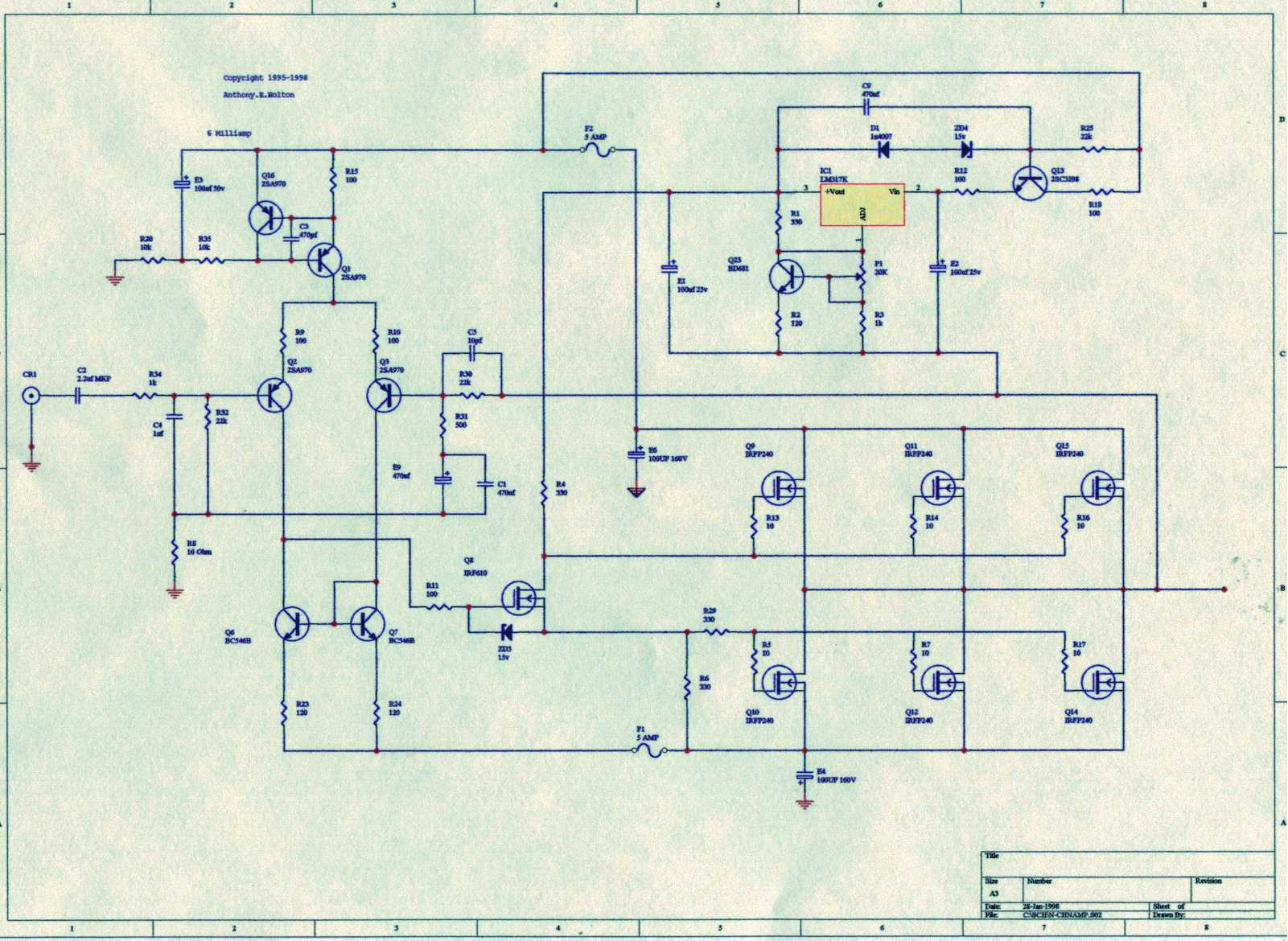
The CIRCLOMOS
Unfortunately, only RF amplifier devices are available, with the lowest frequency being 10 KHz.
The circuit in question pertains to RF (radio frequency) amplification, specifically focusing on devices that operate with a minimum frequency threshold of 10 KHz. RF amplifiers...