


Aircraft band / AM Receiver with PIC16F84
#aircraft band
#AM receiver
#PIC16F84
#frequency synthesizer
#VCO
#PLL
#RF amplifier
#mixer
#communication
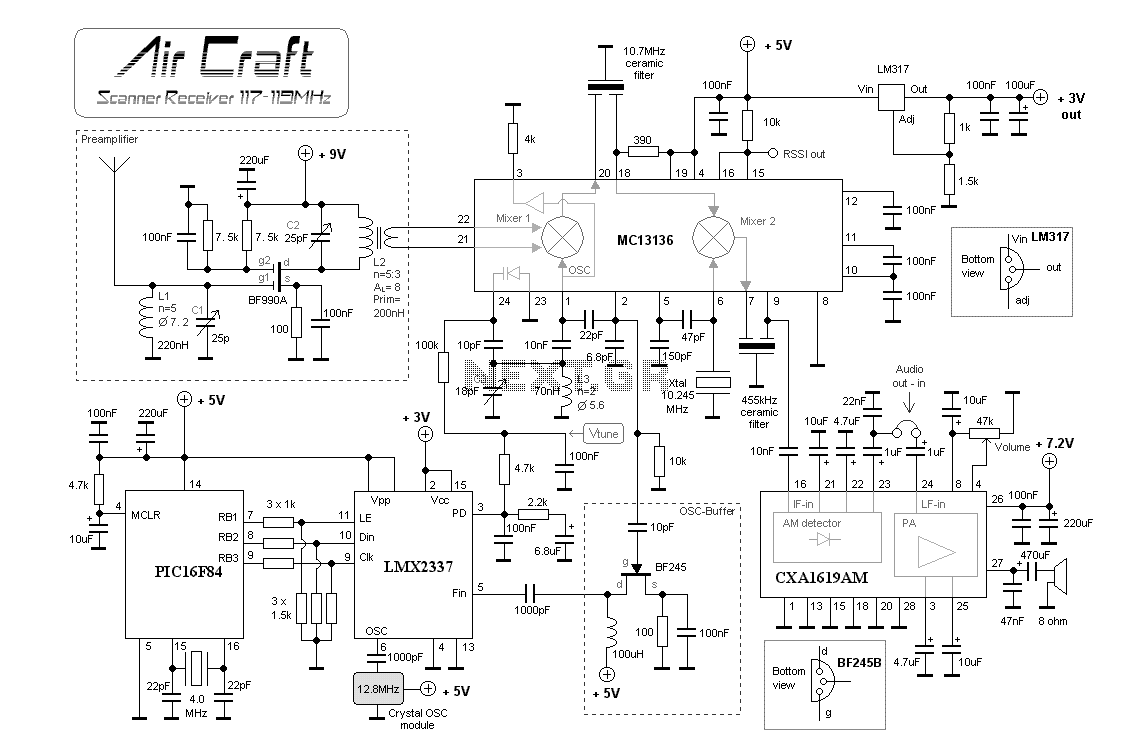
Description: Aircraft communication is still AM modulated and the frequency is about 110-125 MHz. What differs this construction from my two previous is that I have implemented many blocks into one circuit and therefore I will have superior performance with fewer components. The receiver is working with a Frequency Synthesizer which gives very stable reception and it is easy to change frequency as well. The RF signal is first amplified before it enters mixer 1. To mixer 1 is also a VCO (Voltage Controlled Oscillator). The tuning voltage to the oscillator is controlled by the PLL synthesizer. There is also a feedback from the output of the VCO to the PLL synthesizer. The synthesizer will control the VCO-voltage until the frequency is locked to the desired frequency you have programmed into the PIC circuit. The product of mixer 1 is filtered into a standard 10.7 MHz ceramic filter and then enters mixer 2. At mixer 2, the RF will be mixed with a constant frequency from a crystal (10.245 MHz). The product will enter a new ceramic filter and finally into an AM demodulator which brings out the audio.
To the left, you will find the preamplifier. It is based on a dual-gate FET (You can use almost any dual-gate FET). At Gate 1, we have the antenna input. L1 and C1 will tune the antenna for best performance. To find a super perfect antenna match, you can solder the antenna to a tap-point of L1. Gate 2 is biased to give high gain. At the drain, you will find another tuned circuit L2 and C2. This circuit should also be tuned for best performance. L2 is a transformer slug-tuned inductor. An inductor with an AL value of 7 with 5 turns primary will yield 175 nH. This inductor transforms the RF to the secondary side with 3 turns which is connected to mixer 1.
In the MC13136, an oscillator is found at pins 1 and 2. This oscillator is connected to mixer 1. A tuned circuit connected to C3 and L3 enhances this oscillator. To make this oscillator voltage-controlled, a varicap diode is placed between pins 24 and 23. The capacitance of this diode is dependent on the voltage applied across it. A small 10 pF capacitor connects the varicap and C3, allowing frequency adjustment by applying a voltage to pin 24.
In mixer 2, the RF signal flows from mixer 1 through the ceramic filter into mixer 2. At pins 5 and 6, a fixed oscillator with a crystal operates at 10.245 MHz. The 455 kHz IF passes through a ceramic filter to the AM demodulator. At pin 15, a voltage indicates the strength of the input RF signal (RSSI), which can control a squelch unit.
The PLL synthesizer is a critical component in this design. At pin 2, a 10 kΩ resistor is connected to ground to amplify the oscillation current. A fraction of the oscillation energy passes through a 10 pF capacitor to a FET buffer, preventing glitches from the PLL from affecting the VCO and avoiding excessive loading on the VCO. The VCO frequency is amplified at pin 5 of the PLL, while pin 3 serves as the phase detector output. The PLL regulates the current at this pin, and with capacitors and resistors, a voltage is fed back to the varicap at pin 24 of the MC13136 through a 100 kΩ resistor. Monitoring this voltage with a voltmeter will demonstrate how the system maintains frequency lock. Aircraft communication is still AM modulated and the frequency is about 110-125 MHz. What differ this construction from my two previous is that I have implemented many blocks into one circuit and therefore I will have superior performance with less components. The receiver is working with a Frequency Synthesizer which gives a very stable reception and it is easy to change frequency as well.
The RF signal is first amplified before it enters mixer 1. To mixer1 is also a VCO (Voltage Controlled Oscillator). The tuning voltage to the oscillator is controlled by the PLL synthesizer. There is also a feedback from the output of the VCO to the PLL synthesizer. The synthesizer will control the VCO-voltage until the frequency is locked to the desired frequency you have programmed into the PIC circuit. The product of the mixer 1 is filtered into a standard 10.7MHz ceramic filter and then enter mixer 2.
At mixer 2 the RF will be mixed with a constant frequency from a crystal (10.245MHz). The product will enter a new ceramic filter and finally into a AM demodulator which brings out the audio. To the left you will find the preamplifier. It is based on a dualgate fet (You can use almost any dualgate fet). At Gate 1 we have the antenna input. L1 and C1 will tune the antenna for best performance. To find super perfect antenna match you can solder the antenna to a tap-point of L1. I can not tell you where to put the tap, you have to experiment yourself. Gate 2 is biased to give high gain. At drain you will find another tuned circuit L2 and C2. This circuit should also be tuned for best performance. I have chosen L2 to be a transformer slugtuned Inductor. I have an inductor with AL value of 7. With 5 turns primary I will get 5*5*7=175nH. This inductor transform the RF to the secondary side 3 turns which is connected to mixer 1. Mixer 1 and Mixer 2: In the MC13136 you will find an oscillator at pin 1 and 2. This oscillator is connected to mixer 1. To pin 1 and 2 is a tuned circuit connected C3 and L3. How to make this oscillator voltage controlled? Between pin 24 and 23 is a varicap diod. The capacitans of this diod is dependent of the voltage over it. Look at the schematic and you will find a small 10pF capacitor connecting the varicap and the C3. So, by applying a voltage to pin 24 you will now be able to change the frequency a few MHz. Forget about that now and look at mixer 2. You see how the RF signal goes from mixer 1 through the ceramic filter into mixer 2. At pin 5 and 6 you will find a fixed oscillator with a crystall. This oscillator is always 10.245MHz (hopefully). The 455KHz IF is now passing a ceramic filter and to the AM demodulator. At Pin 15 you will have a voltage depending on the strength of the input RF signal (RSSI). This voltage can control a squelsh unit. PLL synthesizer: Many people get scared when it comes to PLL stuff. Don't worry I will explain to you. Earlier I told you that the oscillator was at pin 1 and 2. Well, at pin 2 I have added a 10k resistor to ground because I want to amplify the oscillation current. A fraction of the oscillation energy slips away through a 10pF capacitor down to a FET buffer. This buffer is needed because I don't want glitches from the PLL go back into the VCO and I don't want to load the VCO to much either.
At pin5 of the PLL I will have the VCO frequency amplified. Pin 3 of the PLL is the Phase detector output. The PLL will regulate the current at this pin and with some capacitor and resistor I will have a voltage which is feed back to the varicap at pin 24 of the MC13136 through a 100k resistor. If you want you can probe (schematic Vtune) this voltage with a voltmeter and you will see how it keeps the frequency locked.
To the left, you will find the preamplifier. It is based on a dual-gate FET (You can use almost any dual-gate FET). At Gate 1, we have the antenna input. L1 and C1 will tune the antenna for best performance. To find a super perfect antenna match, you can solder the antenna to a tap-point of L1. Gate 2 is biased to give high gain. At the drain, you will find another tuned circuit L2 and C2. This circuit should also be tuned for best performance. L2 is a transformer slug-tuned inductor. An inductor with an AL value of 7 with 5 turns primary will yield 175 nH. This inductor transforms the RF to the secondary side with 3 turns which is connected to mixer 1.
In the MC13136, an oscillator is found at pins 1 and 2. This oscillator is connected to mixer 1. A tuned circuit connected to C3 and L3 enhances this oscillator. To make this oscillator voltage-controlled, a varicap diode is placed between pins 24 and 23. The capacitance of this diode is dependent on the voltage applied across it. A small 10 pF capacitor connects the varicap and C3, allowing frequency adjustment by applying a voltage to pin 24.
In mixer 2, the RF signal flows from mixer 1 through the ceramic filter into mixer 2. At pins 5 and 6, a fixed oscillator with a crystal operates at 10.245 MHz. The 455 kHz IF passes through a ceramic filter to the AM demodulator. At pin 15, a voltage indicates the strength of the input RF signal (RSSI), which can control a squelch unit.
The PLL synthesizer is a critical component in this design. At pin 2, a 10 kΩ resistor is connected to ground to amplify the oscillation current. A fraction of the oscillation energy passes through a 10 pF capacitor to a FET buffer, preventing glitches from the PLL from affecting the VCO and avoiding excessive loading on the VCO. The VCO frequency is amplified at pin 5 of the PLL, while pin 3 serves as the phase detector output. The PLL regulates the current at this pin, and with capacitors and resistors, a voltage is fed back to the varicap at pin 24 of the MC13136 through a 100 kΩ resistor. Monitoring this voltage with a voltmeter will demonstrate how the system maintains frequency lock. Aircraft communication is still AM modulated and the frequency is about 110-125 MHz. What differ this construction from my two previous is that I have implemented many blocks into one circuit and therefore I will have superior performance with less components. The receiver is working with a Frequency Synthesizer which gives a very stable reception and it is easy to change frequency as well.
The RF signal is first amplified before it enters mixer 1. To mixer1 is also a VCO (Voltage Controlled Oscillator). The tuning voltage to the oscillator is controlled by the PLL synthesizer. There is also a feedback from the output of the VCO to the PLL synthesizer. The synthesizer will control the VCO-voltage until the frequency is locked to the desired frequency you have programmed into the PIC circuit. The product of the mixer 1 is filtered into a standard 10.7MHz ceramic filter and then enter mixer 2.
At mixer 2 the RF will be mixed with a constant frequency from a crystal (10.245MHz). The product will enter a new ceramic filter and finally into a AM demodulator which brings out the audio. To the left you will find the preamplifier. It is based on a dualgate fet (You can use almost any dualgate fet). At Gate 1 we have the antenna input. L1 and C1 will tune the antenna for best performance. To find super perfect antenna match you can solder the antenna to a tap-point of L1. I can not tell you where to put the tap, you have to experiment yourself. Gate 2 is biased to give high gain. At drain you will find another tuned circuit L2 and C2. This circuit should also be tuned for best performance. I have chosen L2 to be a transformer slugtuned Inductor. I have an inductor with AL value of 7. With 5 turns primary I will get 5*5*7=175nH. This inductor transform the RF to the secondary side 3 turns which is connected to mixer 1. Mixer 1 and Mixer 2: In the MC13136 you will find an oscillator at pin 1 and 2. This oscillator is connected to mixer 1. To pin 1 and 2 is a tuned circuit connected C3 and L3. How to make this oscillator voltage controlled? Between pin 24 and 23 is a varicap diod. The capacitans of this diod is dependent of the voltage over it. Look at the schematic and you will find a small 10pF capacitor connecting the varicap and the C3. So, by applying a voltage to pin 24 you will now be able to change the frequency a few MHz. Forget about that now and look at mixer 2. You see how the RF signal goes from mixer 1 through the ceramic filter into mixer 2. At pin 5 and 6 you will find a fixed oscillator with a crystall. This oscillator is always 10.245MHz (hopefully). The 455KHz IF is now passing a ceramic filter and to the AM demodulator. At Pin 15 you will have a voltage depending on the strength of the input RF signal (RSSI). This voltage can control a squelsh unit. PLL synthesizer: Many people get scared when it comes to PLL stuff. Don't worry I will explain to you. Earlier I told you that the oscillator was at pin 1 and 2. Well, at pin 2 I have added a 10k resistor to ground because I want to amplify the oscillation current. A fraction of the oscillation energy slips away through a 10pF capacitor down to a FET buffer. This buffer is needed because I don't want glitches from the PLL go back into the VCO and I don't want to load the VCO to much either.
At pin5 of the PLL I will have the VCO frequency amplified. Pin 3 of the PLL is the Phase detector output. The PLL will regulate the current at this pin and with some capacitor and resistor I will have a voltage which is feed back to the varicap at pin 24 of the MC13136 through a 100k resistor. If you want you can probe (schematic Vtune) this voltage with a voltmeter and you will see how it keeps the frequency locked.

WWV receiver circuit
The RF amplifier Q3 connects to diodes D1 to D4 within the mixer. Transistors Q1 and Q2, through transformers T1 and T2, facilitate the injection of liquid oxygen at 10 MHz for diodes D1, operational amplifier U1A, and U1B. Operational...

Simple Cable TV Amplifier Circuit
This cable TV amplifier circuit is an RF amplifier designed for quick installation between two coaxial cables. Both the input and output impedances are compatible with 75-ohm cables. The main amplifier is the T1 transistor, while T2 functions as an...
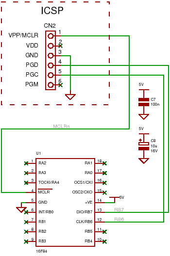
pic16f84
An introduction to the PIC16F84 microcontroller, including connections for an ICSP programmer and a circuit example.
The PIC16F84 is an 8-bit microcontroller from Microchip Technology, widely utilized in various embedded applications due to its versatility and ease of use. It features...

50 to 150MHz high frequency VCO circuit
The Bong circuit is a high-frequency Colpitts oscillator that utilizes a Ge coil (L). It features two heads and is designed for simple production. The frequency of oscillation can be determined, and testing is conducted to ascertain the value of...

PLL Exciter-2
This is a Phase-Locked Loop (PLL) controller designed to operate with a Voltage-Controlled Oscillator (VCO) and modulator. These two modules should be utilized together to create a complete baseband-capable exciter unit. The PLL controller incorporates a stable crystal-controlled reference and...

Q-Switch Driver
The Q-Switch driver for an old YAG laser failed. A replacement was over $1000, so a custom driver was built for less than $300 (see picture and schematic below). The specifications required were at least 20W into a 50-ohm load...

Circuit explanation of PLL synthesizing oscillator
The output frequency can be altered based on the division ratio of the comparison frequency in the 10 kHz unit, with the division ratio set to 1024 in this circuit. Given that the amateur radio bandwidth in Japan is 2...
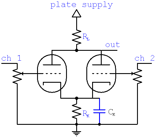
active mixer
The calculator computes the gain and output impedance of a common plate load mixer. Each input channel controls a separate grid, which affects the plate current through the common plate load resistor RL and the cathode resistor RK. The optional...

Small 3-wheel ROBOT with PIC16F84 brain & InfraRed eyes
When the 36 kHz infrared light emitted by the LEDs is reflected off an object, one of the receiver modules is activated. The PIC16F84 microcontroller then directs the robot to avoid the object by reversing one of the motors.
The circuit...