


ALtitude Imaging Entering Near-space
#Yaesu FT-790R
#transceiver
#Radiometrix NTX2
#Atmega
#5V
#TX Input
#near-space
#communication
#wireless
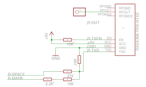
Description: The Yaesu FT-790R is a transceiver that has proven to be efficient and user-friendly. After receiving the device, the team began configuring the Radiometrix NTX2 for proper operation. Operating the Atmega microcontroller at 5V posed challenges because the TX input for the radio operates at an analog level centered around 1.2 volts, where 1.2 volts produces the exact carrier frequency. The single sideband modulation means that a 0.9-volt input results in a frequency that is approximately 400 kHz lower. The team utilized RTTY (Radio Teletype) for communication, where the receiver emits two tones: one for binary 0 (space) and another for binary 1 (mark). They chose a baud rate of 50, following a protocol similar to standard serial interfaces, specifically using 7 data bits, no parity bits, and 1 stop bit. The process involves sending a start bit as a space, followed by the 7 data bits, and concluding with a mark (the stop bit). The radio requires 0.9V for a space and 1.2V for a mark, necessitating a potential divider setup. After configuring the fixed resistors, the radio was tuned, resulting in audible signals. The team connected the radio to a computer using a 3.5mm audio cable and utilized fldigi, an open-source program for decoding amateur radio signals. They successfully transmitted "Hello World" from the Atmega, which was received and displayed on the screen. An improvised antenna was fashioned from a piece of wire, and tests were conducted at a nearby hill, achieving a range of 800 meters before distortion occurred. Further testing with an old laptop confirmed successful decoding at 600 meters. The project faced challenges when attempting to connect to an old mobile phone, which required accessing the UART over USB. An alternative Ericsson model was acquired, which allowed for direct circuit connections. Steps included fixing wires to important pins, implementing a potential divider to accommodate the phone's voltage requirements, and utilizing the Arduino's FTDI chip for initial testing. The AT command protocol was identified as a source of frustration due to differences in line ending characters across operating systems, which led to confusion during communication. Ultimately, the decision was made to use the Atmega162 microcontroller to design the ALIEN Flight Computer, with careful attention to PCB layout and trace width to mitigate manufacturing errors.
The Yaesu FT-790R transceiver is a sophisticated piece of equipment that operates effectively within amateur radio applications. It is designed to facilitate both transmission and reception of signals, utilizing single sideband modulation, which is essential for efficient bandwidth usage. The analog TX input requires precise voltage levels to ensure accurate frequency output, which necessitates careful voltage management through the use of potential dividers.
In this application, the Radiometrix NTX2 is integrated to enable digital communication via RTTY. The protocol employed—7 data bits, no parity, and 1 stop bit—ensures compatibility with standard serial communication practices. The use of a baud rate of 50 allows for reliable transmission of data, specifically formatted to represent binary states through varying voltage levels.
The circuit design involves the careful selection of resistors to create the necessary voltage divider, ensuring that the Atmega microcontroller operates within safe parameters while interfacing with the radio. The connection of the radio to a computer via a 3.5mm audio cable and the utilization of fldigi software for decoding demonstrates the integration of hardware and software in modern amateur radio practices.
Testing procedures included the creation of a makeshift antenna, showcasing the practical aspects of radio transmission and reception. The reported range of 800 meters highlights the effectiveness of the setup, while further tests with a laptop confirmed the system's capabilities under real-world conditions.
The challenges faced during the integration of a mobile phone into the system underscore the complexities of interfacing different hardware components. The transition from a USB-based UART to a direct connection with the Ericsson t68i exemplifies the iterative nature of electronic design, where hardware modifications are often necessary to achieve project goals.
In conclusion, the design of the ALIEN Flight Computer represents a comprehensive approach to integrating various electronic components, emphasizing the importance of careful planning and execution in the development of amateur radio systems. The resulting PCB layout, with its large trace widths, reflects a commitment to reliability and ease of manufacturing, ensuring that the final product meets the required specifications for successful operation.Yaesu FT-790R which, while being the first transceiver we`ve touched, as far as we know is very good! Simrun received the stoic brick and seemed to be able to operate it very easily. Eventually I met up with him and we set about wiring up the Radiometrix NTX2 appropriatly. Because we`re running our Atmega on 5V this proved difficult The TX Inpu t to the radio is analogue and is centered around 1. 2 Volts (ie. giving it 1. 2 volts should produce the exact carrier frequency). It`s single side band, so giving it 0. 9 Volts would result in roughly 400 KHz less. We`re using RTTY which means that the receiver will emit one of two tones at any instant, one meaning a binary 0 (a space`) and one meaning a binary 1 (a mark`). We chose to use baud 50 ie. we send 50 marks/spaces a second, and the protocol` is exactly the same a standard serial interface. We`re using the parameters `7n1 ², meaning 7 data bits (our ASCII), no parity bits, 1 stop` bit. Thus for each byte, send a start` bit as a space, send the 7 data bits, then send a mark (the stop bit).
Then you can repeat the process for another byte or remain at a mark level, the idle state. We had to feed the radio 0. 9V for a space and 1. 2V for a mark it`s potential divider time! Having set that up with fixed resistors, we tuned in the radio and heard a whole load of meaningless beeps but it sounded pretty cool. We grabbed a spare 3. 5mm audio cable, connected radio to computer and started fldigi a super open-source (free) program for decoding anything and everything to do with Amateur Radio.
I had programmed the Atmega to do send Hello World (more on that later) and guess what! Up comes onto the screen Hello World Hello World Hello World`. Success! Aerial to transmit with We grabbed the nearest piece of wire and connected it to the RF OUT most likely a horribly incompatible antenna, but hey. Positioning it by the window we headed out to a nearby hill to see how good the range was, and got 800 metres before the beeps were really distorted.
We also managed to scare and alienate some locals! Simrun decided that whenever we passed someone, he needed to test the radio at maximum volume. Finally, we grabbed my old laptop and went out again to the field, and managed to decode it at 600m we didn`t try 800m because the terrible battery ran out. Bad things happened on the w800i front. It turned out that the AT command UART was only a virtual` one you can only access it over USB. What a pain! Recommended to us by #highaltitude, we headed over to ebay and instead got an oldschool Ericsson, the t68i, which was so old that it had no usb capabilities and the UART was exposed on the bottom so we could hook it up to our circuit easily.
I also got a USB Cable (DKU-11) for the connector which we would hack. Step one: Fix wires to the important pins pin 4 and pin 10. Harder than it sounds! Under the sticker on the DKU cable there`s some screws, which come out really easily. Inside, a circuit board is connected to this metal thing`. Needing to remove the circuit board and get it out of the way, I fetched a hacksaw not the best idea. You need to preserve the very fragile tabs that have solder on them, as otherwise it`s nearly impossible to fix stuff to the pins.
This is a straightforward but fiddely task. If you`re going to try it, good luck! Step two: The phone takes 2. 8V need to divide the Atmega`s 5v in half (roughly). A simple potential dividor will do the trick! I used two 2K7 resistors. Step three: As with the GPS, I hijacked the Arduino`s FTDI chip for the inital testing. And then even worse things happened. It`s 9600 baud, and the AT commands are exactly the same as in the w800i. However, note these pitfalls each one consumed at least 30minutes of me banging my head against a wall: AT protocol needs : There are two characters that represent the end of a line on computers: a Carriage Return and a Line Feed. Windows uses CR then LF on every end of line, Linux just uses LF, and AT required CRLF me being a linux user didn`t notice this, and thus spent lots of time and effort wondering why it wasn`t working.
The AT protocol echos your input by design. On top of the above problem, I was very confused as to why every character I put in was echoed back out of the TX pin (pin 5, which I had connected to debug). This is normal! I decided that it would be a lot simpler and smaller if the huuuge arduino wasn`t taking up space, and set about searching for a suitable Atmega, settling on the Atmega162 because: It has two UARTS (one for the GPS, one for the Phone) and Rapid Electronics didn`t have the Atmega168 in stock.
Armed with this, and all the above work, I had everything I needed to begin designing the ALIEN Flight Computer! Pictures (or PDFs) speak better than words, so I`ve attached the Circuit Schematic and the Final Board Layout.
Because a chemical process (Reading School Electronics Department) would be used to manufacture the PCB, I`ve used huge traces to minimise errors.
The Yaesu FT-790R transceiver is a sophisticated piece of equipment that operates effectively within amateur radio applications. It is designed to facilitate both transmission and reception of signals, utilizing single sideband modulation, which is essential for efficient bandwidth usage. The analog TX input requires precise voltage levels to ensure accurate frequency output, which necessitates careful voltage management through the use of potential dividers.
In this application, the Radiometrix NTX2 is integrated to enable digital communication via RTTY. The protocol employed—7 data bits, no parity, and 1 stop bit—ensures compatibility with standard serial communication practices. The use of a baud rate of 50 allows for reliable transmission of data, specifically formatted to represent binary states through varying voltage levels.
The circuit design involves the careful selection of resistors to create the necessary voltage divider, ensuring that the Atmega microcontroller operates within safe parameters while interfacing with the radio. The connection of the radio to a computer via a 3.5mm audio cable and the utilization of fldigi software for decoding demonstrates the integration of hardware and software in modern amateur radio practices.
Testing procedures included the creation of a makeshift antenna, showcasing the practical aspects of radio transmission and reception. The reported range of 800 meters highlights the effectiveness of the setup, while further tests with a laptop confirmed the system's capabilities under real-world conditions.
The challenges faced during the integration of a mobile phone into the system underscore the complexities of interfacing different hardware components. The transition from a USB-based UART to a direct connection with the Ericsson t68i exemplifies the iterative nature of electronic design, where hardware modifications are often necessary to achieve project goals.
In conclusion, the design of the ALIEN Flight Computer represents a comprehensive approach to integrating various electronic components, emphasizing the importance of careful planning and execution in the development of amateur radio systems. The resulting PCB layout, with its large trace widths, reflects a commitment to reliability and ease of manufacturing, ensuring that the final product meets the required specifications for successful operation.Yaesu FT-790R which, while being the first transceiver we`ve touched, as far as we know is very good! Simrun received the stoic brick and seemed to be able to operate it very easily. Eventually I met up with him and we set about wiring up the Radiometrix NTX2 appropriatly. Because we`re running our Atmega on 5V this proved difficult The TX Inpu t to the radio is analogue and is centered around 1. 2 Volts (ie. giving it 1. 2 volts should produce the exact carrier frequency). It`s single side band, so giving it 0. 9 Volts would result in roughly 400 KHz less. We`re using RTTY which means that the receiver will emit one of two tones at any instant, one meaning a binary 0 (a space`) and one meaning a binary 1 (a mark`). We chose to use baud 50 ie. we send 50 marks/spaces a second, and the protocol` is exactly the same a standard serial interface. We`re using the parameters `7n1 ², meaning 7 data bits (our ASCII), no parity bits, 1 stop` bit. Thus for each byte, send a start` bit as a space, send the 7 data bits, then send a mark (the stop bit).
Then you can repeat the process for another byte or remain at a mark level, the idle state. We had to feed the radio 0. 9V for a space and 1. 2V for a mark it`s potential divider time! Having set that up with fixed resistors, we tuned in the radio and heard a whole load of meaningless beeps but it sounded pretty cool. We grabbed a spare 3. 5mm audio cable, connected radio to computer and started fldigi a super open-source (free) program for decoding anything and everything to do with Amateur Radio.
I had programmed the Atmega to do send Hello World (more on that later) and guess what! Up comes onto the screen Hello World Hello World Hello World`. Success! Aerial to transmit with We grabbed the nearest piece of wire and connected it to the RF OUT most likely a horribly incompatible antenna, but hey. Positioning it by the window we headed out to a nearby hill to see how good the range was, and got 800 metres before the beeps were really distorted.
We also managed to scare and alienate some locals! Simrun decided that whenever we passed someone, he needed to test the radio at maximum volume. Finally, we grabbed my old laptop and went out again to the field, and managed to decode it at 600m we didn`t try 800m because the terrible battery ran out. Bad things happened on the w800i front. It turned out that the AT command UART was only a virtual` one you can only access it over USB. What a pain! Recommended to us by #highaltitude, we headed over to ebay and instead got an oldschool Ericsson, the t68i, which was so old that it had no usb capabilities and the UART was exposed on the bottom so we could hook it up to our circuit easily.
I also got a USB Cable (DKU-11) for the connector which we would hack. Step one: Fix wires to the important pins pin 4 and pin 10. Harder than it sounds! Under the sticker on the DKU cable there`s some screws, which come out really easily. Inside, a circuit board is connected to this metal thing`. Needing to remove the circuit board and get it out of the way, I fetched a hacksaw not the best idea. You need to preserve the very fragile tabs that have solder on them, as otherwise it`s nearly impossible to fix stuff to the pins.
This is a straightforward but fiddely task. If you`re going to try it, good luck! Step two: The phone takes 2. 8V need to divide the Atmega`s 5v in half (roughly). A simple potential dividor will do the trick! I used two 2K7 resistors. Step three: As with the GPS, I hijacked the Arduino`s FTDI chip for the inital testing. And then even worse things happened. It`s 9600 baud, and the AT commands are exactly the same as in the w800i. However, note these pitfalls each one consumed at least 30minutes of me banging my head against a wall: AT protocol needs : There are two characters that represent the end of a line on computers: a Carriage Return and a Line Feed. Windows uses CR then LF on every end of line, Linux just uses LF, and AT required CRLF me being a linux user didn`t notice this, and thus spent lots of time and effort wondering why it wasn`t working.
The AT protocol echos your input by design. On top of the above problem, I was very confused as to why every character I put in was echoed back out of the TX pin (pin 5, which I had connected to debug). This is normal! I decided that it would be a lot simpler and smaller if the huuuge arduino wasn`t taking up space, and set about searching for a suitable Atmega, settling on the Atmega162 because: It has two UARTS (one for the GPS, one for the Phone) and Rapid Electronics didn`t have the Atmega168 in stock.
Armed with this, and all the above work, I had everything I needed to begin designing the ALIEN Flight Computer! Pictures (or PDFs) speak better than words, so I`ve attached the Circuit Schematic and the Final Board Layout.
Because a chemical process (Reading School Electronics Department) would be used to manufacture the PCB, I`ve used huge traces to minimise errors.

Circuit Power transmitter of communitarian wireless TV lm1889 audio and video
This small circuit transmitter processes audio signals from a sound table or microphone, as well as video signals from a camera, DVD, or video cassette. It has a composite video output, allowing direct transmission from a computer over a free...

80 METER CW TRANSCEIVER WITH DIRECT CONVERSION
The RF signal is divided into two signals that are shifted 90 degrees out of phase (one at plus 45 degrees and one at minus 45 degrees). Both signals are then mixed to audio frequencies. The two audio signals are...

6m wireless remote control switch circuit
This example describes a wireless remote control switch featuring reliable operation and practical characteristics, capable of remotely controlling a 6-channel device within a 6-meter range for household electricity. The wireless remote control switch circuit consists of a wireless transmitter and...

30m Band CW-Transceiver
This simple QRP transceiver for the 30 m band did not result from a detailed requirement profile. I simply had some NE592 broadband amplifiers in my junk box, waiting for an application. After performing some tests, that application was quickly...
Wireless On-Off Switch
Typically, home appliances are controlled using switches, sensors, and similar devices. However, physical contact with switches can pose risks, especially in the event of a short circuit. The circuit outlined here eliminates the need for physical contact to operate the...

5V Regulated Power SupplyCircuit
This circuit is a compact +5V power supply that is beneficial for digital electronics experimentation. Inexpensive wall transformers with variable output voltage can be found at electronics shops and supermarkets. While these transformers are readily available, their voltage regulation is...

Wireless-fm-microphone
An adjustable capacitor C10 and a coil L1 create a tank circuit that, along with Q1, C2, and R1, oscillates at a frequency within the FM band. The center frequency is adjustable by tuning C10. An electret microphone, M1, captures...

ems metaboard
Any microcontroller from the ATmegaXX8 family can be utilized, although investing a small amount in additional flash memory is advisable. A DIP socket is technically optional, but its absence is not recommended. A 28-pin DIP socket is somewhat uncommon; if...

Tx/Rx Control
This circuitry offers some features that are highly desirable when building a QRP (or ANY) transceiver. It also includes a combination of features that many might not always take the time to include in their projects. Considerable effort has been...