


AM-FM-TV RF AMPLIFIER
#RF amplifier
#AM-FM-TV
#BF194
#BF198
#coaxial cable
#universal amplifier
#signal amplification
#radio frequency

Description: The circuit is a universal amplifier capable of amplifying any RF signal. The BF194 or BF198 transistors can be utilized. Coaxial cable should be used for connections. Additional components include: R1=22K, R2=100K, R3=18, R4=1.2K, C1=470PF, C2=470PF, C3=1NF, and T=BF194 or BF198.
The universal RF amplifier circuit employs either the BF194 or BF198 transistors, both of which are suitable for high-frequency applications. The circuit is designed to enhance RF signals, making it ideal for various communication tasks, including radio frequency transmission and reception.
The resistors in the circuit include R1 (22KΩ), R2 (100KΩ), R3 (18Ω), and R4 (1.2KΩ). R1 and R2 form a voltage divider that sets the biasing conditions for the transistor, ensuring it operates within its active region for optimal amplification. R3 serves as a load resistor, helping to convert the amplified current from the transistor into a voltage signal. R4 is used for emitter biasing, stabilizing the transistor's operating point against variations in temperature and transistor parameters.
Capacitors C1 (470pF), C2 (470pF), and C3 (1nF) are crucial for coupling and bypassing in the circuit. C1 and C2 are used for AC coupling, allowing the RF signals to pass while blocking any DC components, thus preventing distortion in the amplified signal. C3 serves as a bypass capacitor, helping to maintain a stable voltage across the transistor by filtering out high-frequency noise.
The use of coaxial cable for connections is essential in RF applications to minimize signal loss and interference. Coaxial cable provides a shielded environment for the signal, reducing the impact of external electromagnetic interference, which is critical for maintaining the integrity of the RF signals being amplified.
Overall, this universal amplifier circuit is versatile and can be adapted for various RF applications, making it a valuable tool in the field of electronics and communication systems. Proper assembly and layout are crucial to ensure the circuit functions as intended, with attention paid to component placement and the use of appropriate shielding techniques.The circuit is a universal amplifier that can amplify any rf signal. You can use the BF194 or the BF198. Make sure you use coaxial cable. Parts: R1=22K R2=100K R3=18 R4=1.2K C1=470PF C2=470PF C3=1NF T= BF194 OR BF198
The universal RF amplifier circuit employs either the BF194 or BF198 transistors, both of which are suitable for high-frequency applications. The circuit is designed to enhance RF signals, making it ideal for various communication tasks, including radio frequency transmission and reception.
The resistors in the circuit include R1 (22KΩ), R2 (100KΩ), R3 (18Ω), and R4 (1.2KΩ). R1 and R2 form a voltage divider that sets the biasing conditions for the transistor, ensuring it operates within its active region for optimal amplification. R3 serves as a load resistor, helping to convert the amplified current from the transistor into a voltage signal. R4 is used for emitter biasing, stabilizing the transistor's operating point against variations in temperature and transistor parameters.
Capacitors C1 (470pF), C2 (470pF), and C3 (1nF) are crucial for coupling and bypassing in the circuit. C1 and C2 are used for AC coupling, allowing the RF signals to pass while blocking any DC components, thus preventing distortion in the amplified signal. C3 serves as a bypass capacitor, helping to maintain a stable voltage across the transistor by filtering out high-frequency noise.
The use of coaxial cable for connections is essential in RF applications to minimize signal loss and interference. Coaxial cable provides a shielded environment for the signal, reducing the impact of external electromagnetic interference, which is critical for maintaining the integrity of the RF signals being amplified.
Overall, this universal amplifier circuit is versatile and can be adapted for various RF applications, making it a valuable tool in the field of electronics and communication systems. Proper assembly and layout are crucial to ensure the circuit functions as intended, with attention paid to component placement and the use of appropriate shielding techniques.The circuit is a universal amplifier that can amplify any rf signal. You can use the BF194 or the BF198. Make sure you use coaxial cable. Parts: R1=22K R2=100K R3=18 R4=1.2K C1=470PF C2=470PF C3=1NF T= BF194 OR BF198

TV RF Amplifier 5W Circuit With BLW98
The circuit is designed for driving small UHF TV transmitters, providing a gain of 7 dB and capable of amplifying signals within the frequency range of 470-860 MHz. Key components include resistors, capacitors, and transistors.
This circuit serves as a critical...
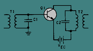
RF amplifier coupling
There are various methods to couple signals from one stage to another. Transformer coupling is the most prevalent technique employed for coupling RF amplifiers. Transformer coupling offers numerous advantages over RC coupling for RF amplifiers; for instance, it utilizes fewer...

WWV receiver circuit
The RF amplifier Q3 connects to diodes D1 to D4 within the mixer. Transistors Q1 and Q2, through transformers T1 and T2, facilitate the injection of liquid oxygen at 10 MHz for diodes D1, operational amplifier U1A, and U1B. Operational...

250mw 16 db vhf amplifier
This project involves a 250mW RF power amplifier circuit. It is designed to amplify the output of approximately 7mW wideband FM transmitters to a final output level of about 250mW. The circuit utilizes a simple two-transistor VHF power amplifier configuration,...

Broadcast-band-rf-amplifier
The circuit features a frequency response ranging from 100 Hz to 3 MHz, with a gain of approximately 30 dB. Field-effect transistor Q1 is configured in a common-source self-biased mode. An optional resistor R1 allows for the adjustment of the...

Circuit for power linear RF amplifier with BLY90
This circuit functions as an RF power amplifier designed to operate with a power supply capable of delivering 13 volts at a current of 10 amperes. Careful assembly of the power source is essential. It utilizes a shielded transformer and...

10w 225-400mhz linear amplifier
This broadband amplifier operates within the 225-400 MHz military communications band, delivering an RF output power of 10 watts while powered by a 28-volt supply. It is suitable for use as a driver for higher power devices such as the...

Dual AC radio remote control switch circuit diagram
The circuit diagram illustrates a dual radio remote control switch system. The transmitter section features Q3, which generates a high-frequency carrier signal, while Q1 and Q2 form the oscillator circuit. Pressing switch SW1 results in an oscillation frequency of 5...

4 watt 900mhz rf amplifier
This RF amplifier circuit delivers a power output of 4 Watts at a frequency of 900 MHz. It utilizes Wilkinson power dividers in the base and collector circuits of transistors Q2 and Q3. Two SD1853 driver application transistors are paralleled...