


AM Synchronous Demodulator
#AM demodulator
#synchronous reception
#local oscillator
#frequency locking
#linear detection
#low noise
#RF circuit
#signal processing
#communication
#receiver

Description: The advantages of synchronous reception of AM signals are well recognized, including high selectivity, linearity of detection, and a lower noise level at the output compared to other reception methods. The circuit diagram is illustrated in Figure 1. The operation of this circuit relies on the direct locking of the local oscillator frequency to the input signal. This method has been validated in a medium wave receiver as described in the literature, yielding favorable results. The proposed detector features a synchronized oscillator utilizing transistors VT1 and VT2, a switching mixer based on transistor VT3, and an audio frequency (AF) filter composed of components L2, C3, and C4. The synchronized oscillator is based on a circuit design proposed by E. Savitsky. Frequency tuning elements C2, R3, and the FET transistor VT1 have been incorporated into this oscillator circuit. When the input signal is applied to the gate of the transistor, it mixes with the local oscillator signal within the transistor's channel. The base current component of transistor VT2 modulates the local oscillator frequency, and once the difference frequency falls within the lock range, the local oscillator transitions from beat mode to sync mode. This alignment ensures that the frequencies of the input signal and local oscillator are equal, resulting in a phase difference of 0° or 180°. The maintenance of frequency and phase equality is facilitated by the DC component of the base current of VT2, which is proportional to the sine of the phase difference. The device operates similarly to a phase-locked loop (PLL) system, with the distinction being a 90° phase shift in sync mode for PLL systems. The output voltage from the local oscillator manifests as switching pulses, which are directed to the gate of transistor VT3, facilitating its switching operation. The voltage envelope of the AM signal passes through the AF filter to an audio amplifier, with the detector gain set at 0.25 times. The local oscillator can synchronize with input signals as low as hundreds of microvolts. Experiments conducted with this detector successfully received AM signals from the medium wave band. A resonant tank circuit tuned to the medium wave frequency was connected to the input of the detector circuit, and the demodulated signal was processed through a two-stage audio amplifier. Utilizing a 3-meter indoor antenna and proper grounding, good-quality signals from radio stations located 200-250 km away were received. Coarse frequency adjustments for the local oscillator in the range of 630-860 kHz are achieved with potentiometer R3, while variable capacitor C2 allows for fine-tuning within ±15 kHz. Adjustments to R3 affect the amplitude of the pulses, which do not drop below 3.5 V. The cut-off voltage for the KP103J transistor is 0.5-2.2 V, ensuring that the detector's gain remains relatively constant across the operating frequency range of the local oscillator. To enhance the dynamic range of the detector and minimize crosstalk and intermodulation interference, a resistor can be added to the drain network of transistor VT3, functioning as an attenuator. The value of this resistor should be determined based on specific reception conditions. The detector operates on a stabilized and well-filtered voltage supply, with a current consumption of approximately 2.5 mA. The coil L1 is constructed on a toroidal ferrite core K7x4x2 with a magnetic permeability of 600, consisting of 52 turns of 0.2 mm diameter enameled copper wire (AWG 32), and includes a center tap. Shielding of the coil is recommended, such as by wrapping it in conductive material.
The circuit design leverages the principles of synchronous detection to achieve enhanced performance in AM signal reception. The synchronized oscillator, which is the heart of the circuit, ensures that the local oscillator frequency is locked to the input signal frequency, enabling precise demodulation of the AM signal. The careful selection of components, such as the specific transistors and tuning elements, contributes to the overall effectiveness of the design. The integration of the AF filter ensures that only the desired audio frequencies are amplified, further improving signal clarity. The use of a resonant tank circuit allows for effective tuning and reception of signals across a specified frequency range, making the circuit suitable for various medium wave applications. The design's ability to maintain stable operation under varying conditions, along with its low power consumption, makes it a viable option for portable or battery-operated devices. Proper assembly and shielding techniques will enhance performance by reducing unwanted interference and noise, ensuring that the received audio signals are of high quality and fidelity.The advantage of synchronous reception of AM signals is widely known. It includes high selectivity, linearity of detection and a low noise level at the output compared to other ways of reception. The circuit diagram is shown in figure 1. The operation of the circuit is based on method of direct locking of the local oscillator frequency by the inpu
t signal. This method has been tested by the author in the medium wave receiver as described in [1], and showed good results. The proposed detector consists of a synchronized oscillator based on the transistors VT1 and VT2, a switching mixer based on the transistor VT3 and an AF filter L2C3C4.
Synchronized oscillator is made on the basis of the oscillator circuit (Fig. 2), proposed by E. Savitsky [2]. The frequency tuning elements C2, R3 and the FET transistor VT1 has been added to this oscillator circuit. When the input signal is applied to the gate of the transistor, the input signal mixing with the signal of the local oscillator in the transistor`s channel.
The component of the base current of the transistor VT2 modulates the signal of the local oscillator frequency, and when the difference frequency becomes equal to the lock range, then the local oscillator switches from the beat mode to the sync mode. This establishes the equality of the input signal frequency and the local oscillator frequency, and the phase difference between voltage of the input signal and the local oscillator † becomes equal to 0 ° or 180 °.
The equality of the frequencies and phases is maintained by the DC component of the base current of VT2, the DC component is proportional to the sin †. As you can see, the device works in the same way as a system PLL, the difference is only in the phase shift, for a PLL system the phase shift is 90 ° in sync mode.
The voltage at the output of the local oscillator has the form of the switching pulses (Fig. 3). This pulses goes to the gate of the transistor VT3, they provide a switching mode of its operation. The voltage envelope of AM signal goes through the AF filter to am audio amplifier. The gain of the detector is 0. 25 times. The local oscillator can be synchronized by a signal with a voltage of hundreds of microvolts. The author conducted an experiment with this detector, in which AM signals of MW band has been received. To do this, a resonant tank circuit tuned to a frequency of MW band has been connected to the the input of the detector circuit, and the demodulated signal was applied to the two-stage audio amplifier [1].
By using the indoor antenna with length of 3 m and the grounding has been received with good quality a signals of a radio stations located at 200. 250 km from the reception site. The coarse adjustment of the local oscillator`s frequency in the range 630. 860 kHz is provided by the potentiometer R3. With the variable capacitor C2 is possible to vary the frequency of the local oscillator within + -15 kHz.
While adjusting the frequency with the resistor R3 the amplitude of the pulses changes. However, it does not drop below 3. 5 V. The cut-off voltage of the transistor KP103J is 0. 5. 2. 2 V, so in the entire operating frequency range of the local oscillator the gain of the detector remains practically unchanged. To expand the dynamic range of the detector and reduce the crosstalk and intermodulation interference it is useful to a resistor in the drain network of the transistor VT3.
This resistor will works as an attenuator. The value of this resistor is chosen based on the specific conditions of reception. The detector is powered by a stabilized and carefully smoothed voltage. The current consumption of the circuit is about 2. 5 mA. The coil L1 is wound on the toroidal ferrite core K7x4x2 600NN (the magnetic permeability is 600), the coil has 52 turns of enameled copper wire of 0. 2 mm (AWG 32) in diameter, the coil has a center tap. It is desirable to shield the coil, for example, wrapp
The circuit design leverages the principles of synchronous detection to achieve enhanced performance in AM signal reception. The synchronized oscillator, which is the heart of the circuit, ensures that the local oscillator frequency is locked to the input signal frequency, enabling precise demodulation of the AM signal. The careful selection of components, such as the specific transistors and tuning elements, contributes to the overall effectiveness of the design. The integration of the AF filter ensures that only the desired audio frequencies are amplified, further improving signal clarity. The use of a resonant tank circuit allows for effective tuning and reception of signals across a specified frequency range, making the circuit suitable for various medium wave applications. The design's ability to maintain stable operation under varying conditions, along with its low power consumption, makes it a viable option for portable or battery-operated devices. Proper assembly and shielding techniques will enhance performance by reducing unwanted interference and noise, ensuring that the received audio signals are of high quality and fidelity.The advantage of synchronous reception of AM signals is widely known. It includes high selectivity, linearity of detection and a low noise level at the output compared to other ways of reception. The circuit diagram is shown in figure 1. The operation of the circuit is based on method of direct locking of the local oscillator frequency by the inpu
t signal. This method has been tested by the author in the medium wave receiver as described in [1], and showed good results. The proposed detector consists of a synchronized oscillator based on the transistors VT1 and VT2, a switching mixer based on the transistor VT3 and an AF filter L2C3C4.
Synchronized oscillator is made on the basis of the oscillator circuit (Fig. 2), proposed by E. Savitsky [2]. The frequency tuning elements C2, R3 and the FET transistor VT1 has been added to this oscillator circuit. When the input signal is applied to the gate of the transistor, the input signal mixing with the signal of the local oscillator in the transistor`s channel.
The component of the base current of the transistor VT2 modulates the signal of the local oscillator frequency, and when the difference frequency becomes equal to the lock range, then the local oscillator switches from the beat mode to the sync mode. This establishes the equality of the input signal frequency and the local oscillator frequency, and the phase difference between voltage of the input signal and the local oscillator † becomes equal to 0 ° or 180 °.
The equality of the frequencies and phases is maintained by the DC component of the base current of VT2, the DC component is proportional to the sin †. As you can see, the device works in the same way as a system PLL, the difference is only in the phase shift, for a PLL system the phase shift is 90 ° in sync mode.
The voltage at the output of the local oscillator has the form of the switching pulses (Fig. 3). This pulses goes to the gate of the transistor VT3, they provide a switching mode of its operation. The voltage envelope of AM signal goes through the AF filter to am audio amplifier. The gain of the detector is 0. 25 times. The local oscillator can be synchronized by a signal with a voltage of hundreds of microvolts. The author conducted an experiment with this detector, in which AM signals of MW band has been received. To do this, a resonant tank circuit tuned to a frequency of MW band has been connected to the the input of the detector circuit, and the demodulated signal was applied to the two-stage audio amplifier [1].
By using the indoor antenna with length of 3 m and the grounding has been received with good quality a signals of a radio stations located at 200. 250 km from the reception site. The coarse adjustment of the local oscillator`s frequency in the range 630. 860 kHz is provided by the potentiometer R3. With the variable capacitor C2 is possible to vary the frequency of the local oscillator within + -15 kHz.
While adjusting the frequency with the resistor R3 the amplitude of the pulses changes. However, it does not drop below 3. 5 V. The cut-off voltage of the transistor KP103J is 0. 5. 2. 2 V, so in the entire operating frequency range of the local oscillator the gain of the detector remains practically unchanged. To expand the dynamic range of the detector and reduce the crosstalk and intermodulation interference it is useful to a resistor in the drain network of the transistor VT3.
This resistor will works as an attenuator. The value of this resistor is chosen based on the specific conditions of reception. The detector is powered by a stabilized and carefully smoothed voltage. The current consumption of the circuit is about 2. 5 mA. The coil L1 is wound on the toroidal ferrite core K7x4x2 600NN (the magnetic permeability is 600), the coil has 52 turns of enameled copper wire of 0. 2 mm (AWG 32) in diameter, the coil has a center tap. It is desirable to shield the coil, for example, wrapp

Simple receiver with microvolt sensitivity
The three-transistor circuit costs less than $10 to build, uses commonly available components, and consumes less than 10 mA from a single 9V battery. By winding coil L1 as shown, the circuit can receive signals in the 5 to 15...

The equivalent circuit and a local oscillator
The local oscillator operates at frequencies of 1 GHz or higher, utilizing a common collector circuit, which makes it challenging to generate low-frequency self-oscillation. Typically, the local oscillator signal is passed through a buffer amplifier stage before being applied to...
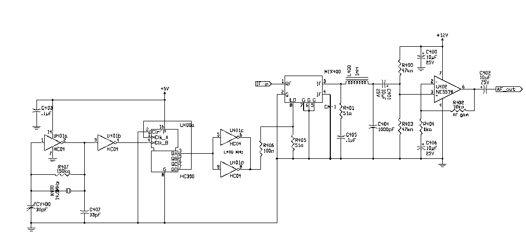
136 kHz QRSS receiver
For digital modes, the ideal receiver should be straightforward, featuring front-end selectivity, manually adjustable gain, and an IF filter. Many functionalities found in HF receivers can be implemented through software. In the collection of components, there was a surplus 1.4...
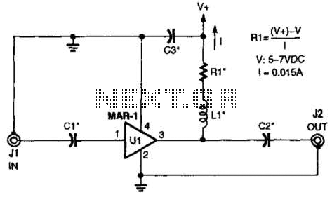
Receiver/Scanner Preamp Circuit
The low-cost Mini-Circuits MAR-X series of chips provides a significant advantage for RF builders, featuring inherent 50-ohm input and output impedances essential for RF systems. An MAR-1-based receiver/scanner preamplifier is illustrated. Capacitors Ci and C2 are chip capacitors, with values...

Receiver Audio Circuit
This simple receiver AF amplifier can supply several hundred milliwatts to an 8-ohm speaker. The gain is approximately 200X. If high gain is not required, C2 can be removed, resulting in a gain of 20. R1 and C6 are essential...

The R2 Single Sideband Direct Conversion Receiver
The old common-base audio preamp, which has a noise figure of 5 dB, is a clear candidate for improvement in noise performance. A common-emitter configuration with shunt feedback provides an input resistance of 50 ohms, which is preferred by the...

MK414 SW Receiver
The original data sheet for the MK414 indicates that the maximum working frequency is approximately 4 MHz. SW transmissions are sufficiently strong that this receiver can effectively operate with signals up to about 6 or 7 MHz. A 10k resistor...

Receiver monitor
The alarm connects to the earphone jack on a receiver. When a signal, typically sent to the headphones, is detected and applied to the gate of SCR1, it conducts, activating the alarm connected to SOI. The signaling device can be...
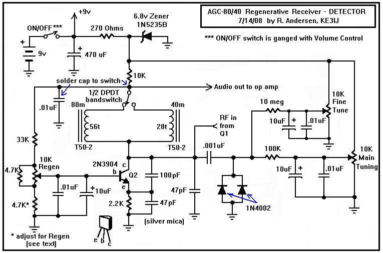
A Regenerative Receiver with AGC for 80 and 40 Meters
Here is a dual-band regenerative receiver that originated from encouraging communications with Jerry (K9UT) and another individual named Harvey, who constructed the original AGC-80 and its experimental successor, the AGC-80/30. Jerry has expressed his satisfaction with both receivers, noting their...