


Atv Downconverter Circuit
#RF converter
#amateur TV
#420-450 MHz
#VHF
#RF amplifier
#mixer
#IF amplifier
#TV receiver
#signal conversion

Description: This RF converter converts amateur TV signals in the 420 to 450 MHz region to VHF channel 3 or 4, allowing reception of those signals on a standard TV receiver. RF amplifier Q1 feeds mixer M1, and Q3 acts as an IF amplifier. Q2 is an oscillator operating around 378 MHz and is tunable over about a 30 MHz range.
The RF converter is designed to facilitate the reception of amateur television signals within the specified frequency range of 420 to 450 MHz by converting these signals to VHF channels 3 or 4. This conversion enables standard television receivers to process and display the amateur TV signals effectively.
The circuit architecture includes several critical components. The RF amplifier (Q1) serves to boost the incoming RF signals before they are fed into the mixer (M1). The mixer is essential for down-converting the frequency of the RF signals to an intermediate frequency (IF) that can be further processed. The output of the mixer is then amplified by the IF amplifier (Q3), which ensures that the signal remains strong enough for subsequent stages of processing.
An important feature of this RF converter is the oscillator (Q2), which operates around 378 MHz. This oscillator is tunable over a range of approximately 30 MHz, allowing for flexibility in the conversion process. The tuning capability is crucial for accommodating variations in the incoming signal frequencies, ensuring optimal performance and signal clarity.
Overall, this RF converter circuit is an effective solution for receiving amateur TV signals, utilizing a combination of amplification, mixing, and tuning to provide a reliable output compatible with standard television equipment. This RF converter converts amateur TV signals in the 420- to 450-MHz region to VHF channel 3 or 4, allowing reception of those signals on a standard TV receiver. RF amplifier Ql feeds mixer Ml, and Q3 acts as an IF amplifier. Q2 is an oscillator operating around 378 MHz and is tuneable over about a 30-MHz range.
The RF converter is designed to facilitate the reception of amateur television signals within the specified frequency range of 420 to 450 MHz by converting these signals to VHF channels 3 or 4. This conversion enables standard television receivers to process and display the amateur TV signals effectively.
The circuit architecture includes several critical components. The RF amplifier (Q1) serves to boost the incoming RF signals before they are fed into the mixer (M1). The mixer is essential for down-converting the frequency of the RF signals to an intermediate frequency (IF) that can be further processed. The output of the mixer is then amplified by the IF amplifier (Q3), which ensures that the signal remains strong enough for subsequent stages of processing.
An important feature of this RF converter is the oscillator (Q2), which operates around 378 MHz. This oscillator is tunable over a range of approximately 30 MHz, allowing for flexibility in the conversion process. The tuning capability is crucial for accommodating variations in the incoming signal frequencies, ensuring optimal performance and signal clarity.
Overall, this RF converter circuit is an effective solution for receiving amateur TV signals, utilizing a combination of amplification, mixing, and tuning to provide a reliable output compatible with standard television equipment. This RF converter converts amateur TV signals in the 420- to 450-MHz region to VHF channel 3 or 4, allowing reception of those signals on a standard TV receiver. RF amplifier Ql feeds mixer Ml, and Q3 acts as an IF amplifier. Q2 is an oscillator operating around 378 MHz and is tuneable over about a 30-MHz range.
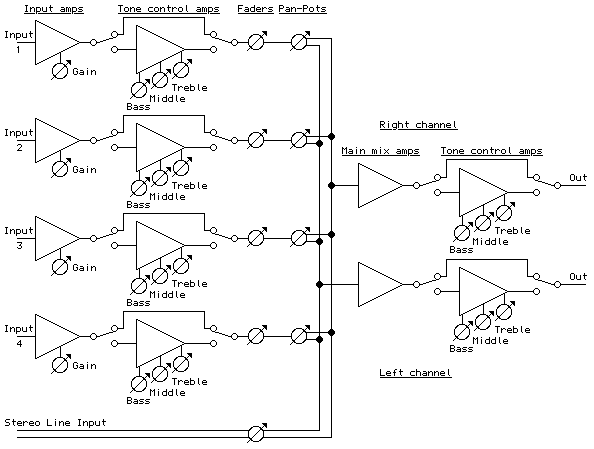
9 Volt Portable Mixer Circuit
The objective of this project was to design a small portable mixer powered by a 9V PP3 battery while maintaining performance quality. The mixer consists of three main modules that can be varied in number and can be adapted to...

1 Watt 2.3 GHz RF Amplifier Using a MRF2001
This is an image Schematic. No Description available.
The provided input indicates the existence of a schematic image without further descriptive content. In the context of electronic schematics, such images typically represent the arrangement and interconnection of various electronic components,...

tv power amplifier schematic
TV RF Power Amplifier 14W. This RF power amplifier operates within the frequency range of 470 - 860 MHz, covering UHF Band IV and V, and delivers an output power of 14 Watts with an input power of 1.5 Watts....
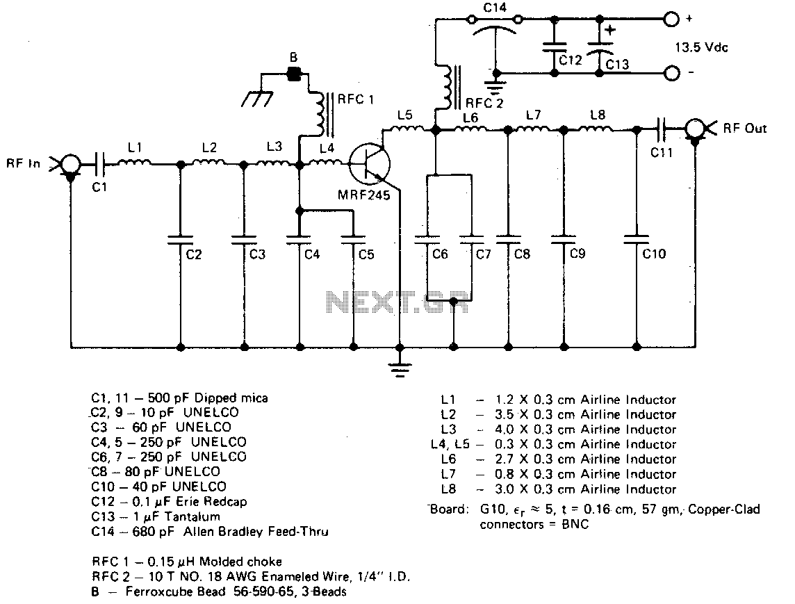
Single-device 80 w 50 ohm vhf amplifier
The amplifier utilizes a single MRF245 transistor and delivers 80 W of output power with a gain of 9.4 dB across the frequency range of 143 to 156 MHz.
The circuit design for the amplifier featuring the MRF245 transistor is intended...

remote control
At certain times of the year, migration occurs a bit north of Southampton to an area where VHF ham operators are sparse and often experience interference. The local repeater utilizes a tone burst, and the proximity to noisy power lines...
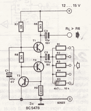
Simple mixer circuit
The simple mixer schematic is based on the common base principle, where input voltages are transformed into alternating currents that are summed to form the output.
The simple mixer circuit utilizes the common base configuration of a transistor, which is characterized...

Portable Mixers
Portable mixer with a high-quality modular design. Powered by a 9V battery, it features very low current consumption. The device integrates a preamplifier, tone control, and mixer functionalities into a single unit, making it an ideal electronics project. Circuit diagram...
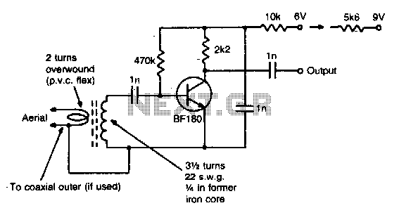
Vhf preamplifier
This simple circuit provides a gain of 15 dB and can be mounted on a 1 inch by 2 inch PCB. Coil specifications are provided for a frequency range of 85 to 95 MHz. For other frequencies, the coil should...

Custom DJ Karaoke Mixer/Scratch Pad/Laptop
After careful consideration and review of feedback, adjustments have been made to the project plans to include or remove certain functions. This project has already accumulated several developments.
The project in question appears to involve a systematic approach to electronic design,...