


Bug-tracer
#rf-injector
#AM receiver
#transistor
#oscillator
#piezoelectric resonator
#wire tracing
#455-kHz
#two-transistor
#detector

Description: The bug tracer consists of a simple RF injector circuit made up of transistors Q1 and Q2, along with a pocket-sized AM broadcast receiver. This two-transistor RF injector circuit provides a constant RF signal to one end of a cable. The AM receiver functions as a detector, enabling the user to trace the cable back to its source. Transistor Q1, in conjunction with a piezoelectric ceramic resonator RES1, forms a basic RF oscillator that operates at or near the AM radio's 455 kHz intermediate frequency. Consequently, the second or third harmonic signals can be easily detected by the receiver. Transistor Q2 is configured in an emitter-follower arrangement to protect the oscillator from output loading, which helps stabilize the output frequency and signal level.
The bug tracer circuit is designed for efficient detection of RF signals along a cable, making it a valuable tool for troubleshooting and locating faults in wiring systems. The RF injector circuit, primarily composed of two transistors, serves as the heart of the device, generating a stable RF signal. Transistor Q1 operates as an oscillator, utilizing the piezoelectric ceramic resonator RES1 to determine the frequency of oscillation. This resonator is critical in producing a consistent frequency output, which is essential for effective signal tracing.
The AM broadcast receiver is employed to detect the RF signal generated by the injector circuit. It is sensitive enough to pick up harmonics of the fundamental frequency produced by the oscillator, which enhances the tracing capability of the device. As the signal travels through the cable, it can be detected at various points, allowing the user to identify the source of the signal or any interruptions in the cable.
The emitter-follower configuration of transistor Q2 plays a significant role in maintaining the integrity of the signal. This arrangement ensures that the oscillator is not adversely affected by variations in load impedance, which can lead to frequency drift and signal degradation. By isolating the oscillator from the load, Q2 helps maintain a stable output frequency and consistent signal strength, improving the overall performance of the bug tracer.
In summary, the bug tracer circuit is an effective solution for tracing RF signals in cables, utilizing a straightforward design that leverages the properties of transistors and resonators. Its compact size and ease of use make it an ideal tool for both professionals and hobbyists in the field of electronics.The bug tracer is made up of a simple rf-injector circuit consisting of Ql and Q2, and a pocketsize, AM broadcast receiver. The two-transistor rf-injector circuit supplies a constant rf signal to one end of a cable. Then the AM receiver is used as a detector, allowing you to trace the wire to its source. Transistor Ql, along with piezoelectric ceramic resonator RESl, make up a simple rf oscillator that operates either at or near the AM-radio, 455-kHz, i-f frequency.
That means that the second or third harmonic signal can easily be picked up by the receiver. Transistor Q2 is connected to an emitterfollower circuit to protect the oscillator from output loading; that helps to stabilize the output frequency and signal level.
The bug tracer circuit is designed for efficient detection of RF signals along a cable, making it a valuable tool for troubleshooting and locating faults in wiring systems. The RF injector circuit, primarily composed of two transistors, serves as the heart of the device, generating a stable RF signal. Transistor Q1 operates as an oscillator, utilizing the piezoelectric ceramic resonator RES1 to determine the frequency of oscillation. This resonator is critical in producing a consistent frequency output, which is essential for effective signal tracing.
The AM broadcast receiver is employed to detect the RF signal generated by the injector circuit. It is sensitive enough to pick up harmonics of the fundamental frequency produced by the oscillator, which enhances the tracing capability of the device. As the signal travels through the cable, it can be detected at various points, allowing the user to identify the source of the signal or any interruptions in the cable.
The emitter-follower configuration of transistor Q2 plays a significant role in maintaining the integrity of the signal. This arrangement ensures that the oscillator is not adversely affected by variations in load impedance, which can lead to frequency drift and signal degradation. By isolating the oscillator from the load, Q2 helps maintain a stable output frequency and consistent signal strength, improving the overall performance of the bug tracer.
In summary, the bug tracer circuit is an effective solution for tracing RF signals in cables, utilizing a straightforward design that leverages the properties of transistors and resonators. Its compact size and ease of use make it an ideal tool for both professionals and hobbyists in the field of electronics.The bug tracer is made up of a simple rf-injector circuit consisting of Ql and Q2, and a pocketsize, AM broadcast receiver. The two-transistor rf-injector circuit supplies a constant rf signal to one end of a cable. Then the AM receiver is used as a detector, allowing you to trace the wire to its source. Transistor Ql, along with piezoelectric ceramic resonator RESl, make up a simple rf oscillator that operates either at or near the AM-radio, 455-kHz, i-f frequency.
That means that the second or third harmonic signal can easily be picked up by the receiver. Transistor Q2 is connected to an emitterfollower circuit to protect the oscillator from output loading; that helps to stabilize the output frequency and signal level.
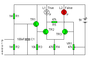
lie detector
The circuit diagram of the Lie Detector consists of three transistors (TR1 to TR3), a capacitor (C1), two LEDs (L1 & L2), five resistors (R1 to R5), and a variable resistor (VR1). Suitable transistors include BC547, BC548, or BC549, or...

Single transistor audio mixer
Numerous audio mixer circuits have been published; however, this particular design is among the simplest. This straightforward audio mixer circuit utilizes only a single transistor. The base-emitter junction of the transistor is biased with diodes D1 and D2. The signals...

Transistor Organ
This simple circuit can provide hours of enjoyment as you learn tunes, play duets or just make some really weird sounds by pushing all the buttons at once. You have probably seen this circuit before, it is fairly common. I...
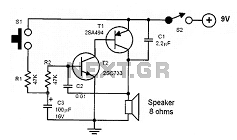
Noise making circuits
The core of the circuit is a two-transistor flasher with frequency modulation applied to the base of the first transistor. When the pushbutton is pressed, the oscillation frequency increases to a peak, and upon release, the frequency decreases due to...

Simple Metronome using transistor
This circuit is a simple metronome model designed for ease of use. It employs transistors as key components, specifically configured as an astable multivibrator, to produce a beeping sound. The tone can be adjusted using a variable resistor (VR1). A...

Transistor Common Base Amplifier
In terms of AC signals, the base is connected to the ground through capacitor C3. Consequently, both the input and output are linked to the base, forming a common base amplifier configuration.
The common base amplifier is a type of transistor...

basic transistor circuits for beginners explored
This article compiles small transistor circuits and configurations suitable for beginners, including current amplifiers, limiters, oscillators, and latches. A simple current amplifier circuit can be constructed using just a couple of NPN transistors. Additionally, two transistors and resistors can be...

DARLINGTON LOGIC PROBE
A two-transistor Darlington connection offers a very high input impedance, ensuring that it does not load the logic circuit being monitored. This configuration drives an LED that illuminates when a logic high (1) is present at the input.
The two-transistor Darlington...

Hands-free-telephone
Transistor Q1 in the headset amplifier circuit amplifies the 30 mV signal intended for the earphones to 0.5 V, which is sufficient to drive stereo earphones. Capacitor C1 blocks any DC current from shorting back into the telephone base. Capacitor...